| CPC A61G 1/0268 (2013.01) [A61G 1/0237 (2013.01); A61G 7/05 (2013.01)] | 19 Claims |

|
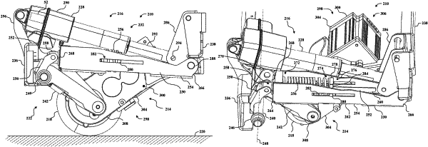
1. A patient transport apparatus comprising:
a support structure arranged for movement along a floor surface;
a support wheel coupled to the support structure, with the support wheel being swivelable about a swivel axis; and
an auxiliary wheel system including:
a support frame coupled to the support structure and including a first cross-member and a second cross-member spaced a distance from the first cross-member along a longitudinal axis;
an auxiliary wheel assembly coupled to the support frame and positionable between a deployed position engaging the floor surface and a stowed position spaced [[a]] from the floor surface, the auxiliary wheel assembly including:
an auxiliary wheel configured to influence motion of the patient transport apparatus over a floor surface,
a motor assembly coupled to the auxiliary wheel and having a motor assembly housing and a motor positioned within the motor assembly housing and coupled to the auxiliary wheel for providing motive power to the auxiliary wheel,
a crank shaft rotatably coupled to the first cross-member of the support frame, and a wheel support frame extending radially outwardly from the crank shaft and coupled to the auxiliary wheel such that a rotation of the crank shaft causes a vertical movement of the auxiliary wheel; and
an actuator assembly coupled to the support frame and to the auxiliary wheel, the actuator assembly including:
a lift actuator operable to move the auxiliary wheel to the deployed position and to the stowed position; and
a spring cartridge assembly configured to bias the auxiliary wheel towards the deployed position.
|