| CPC A61B 17/282 (2013.01) [A61B 17/1285 (2013.01); A61B 17/2804 (2013.01); A61B 17/285 (2013.01); A61B 17/2833 (2013.01); A61B 17/2909 (2013.01); A61B 18/149 (2013.01); A61B 18/1445 (2013.01); A61B 90/03 (2016.02); B23K 26/21 (2015.10); A61B 17/29 (2013.01); A61B 17/295 (2013.01); A61B 18/1442 (2013.01); A61B 18/1447 (2013.01); A61B 2017/2845 (2013.01); A61B 2017/2901 (2013.01); A61B 2017/2902 (2013.01); A61B 2017/292 (2013.01); A61B 2017/2903 (2013.01); A61B 2017/2908 (2013.01); A61B 2017/2912 (2013.01); A61B 2017/2916 (2013.01); A61B 2017/2917 (2013.01); A61B 2017/2919 (2013.01); A61B 2017/2925 (2013.01); A61B 2017/2926 (2013.01); A61B 2017/2933 (2013.01); A61B 2017/2936 (2013.01); A61B 2017/2945 (2013.01); A61B 2017/2946 (2013.01); A61B 2017/2947 (2013.01); A61B 2017/2948 (2013.01); A61B 2017/320052 (2013.01); A61B 2017/320095 (2017.08); A61B 2018/0063 (2013.01); A61B 2018/0091 (2013.01); A61B 2018/00148 (2013.01); A61B 2018/00196 (2013.01); A61B 2018/00202 (2013.01); A61B 2018/00309 (2013.01); A61B 2018/00345 (2013.01); A61B 2018/00601 (2013.01); A61B 2018/00636 (2013.01); A61B 2018/00916 (2013.01); A61B 2018/00946 (2013.01); A61B 2018/00952 (2013.01); A61B 2018/1412 (2013.01); A61B 2018/1455 (2013.01); A61B 2018/1457 (2013.01); A61B 2090/034 (2016.02)] | 13 Claims |

|
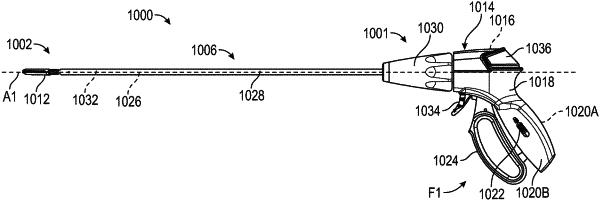
1. A surgical tool comprising:
an outer shaft extending along a longitudinal axis;
a guide fixedly connected to the outer shaft;
an end effector connected to the outer shaft distal of the guide;
a drive shaft located within the outer shaft, extending along the longitudinal axis, and connected to the end effector, the drive shaft translatable with respect to the outer shaft to operate the end effector, and the drive shaft engageable with the guide to limit axial translation along the longitudinal axis of the drive shaft with respect to the outer shaft, the drive shaft including axial tracks respectively located on opposite sides of the drive shaft, the axial tracks to engage the guide; and
a blade located within the drive shaft and translatable therein, the blade extending along the longitudinal axis, the blade including a blade track, the guide extending through the blade track, the blade track having a length longer than a length of the axial tracks to permit translation of the blade with respect to the outer shaft without being stopped or limited by an end of an axial track.
|