| CPC A61B 17/0469 (2013.01) [A61B 17/0485 (2013.01); A61B 17/0487 (2013.01); A61B 17/0467 (2013.01); A61B 2017/00243 (2013.01); A61B 2017/00358 (2013.01); A61B 2017/0488 (2013.01); A61F 2/2457 (2013.01)] | 8 Claims |

|
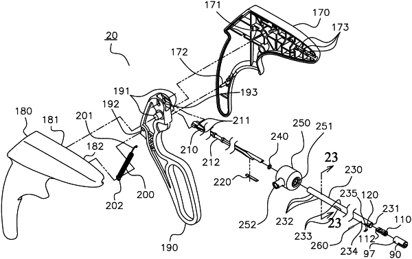
1. A surgical suturing instrument comprising:
a handle;
an actuator on the handle;
an elongated shaft extending distally from the handle along a shaft axis from a proximal end to a distal end, the shaft including one or more fluid apertures disposed between an outer surface of the shaft and an inner surface of the shaft, wherein the inner surface of the shaft at least partially defines an interior portion of the shaft;
an elongated wedge tip at least partially disposed in the interior portion of the shaft, the wedge tip extending along a wedge tip axis from a proximal end to a distal end, wherein the proximal end of the wedge tip is coupled to the actuator, wherein one or more fluid troughs are each defined by one or more exterior surfaces of the wedge tip, each of the one or more fluid troughs extending along the wedge tip axis from a proximal end to a distal end that is at the distal end of the wedge tip, and wherein when the actuator is in a first position, the distal end of the wedge tip is in an unactuated position and when the actuator is in a second position, the distal end of the wedge tip is in an actuated position;
a crimper assembly configured to crimp a suture fastener, the crimper assembly disposed adjacent the distal end of the shaft, the crimper assembly comprising:
a suture fastener receiver configured to receive the suture fastener, the suture fastener receiver extending from a first end to a second end along a receiver axis that is parallel to the shaft axis such that the suture fastener is configured to be inserted into the suture fastener receiver along the receiver axis; and
a hammer anvil, wherein the distal end of the wedge tip selectively engages a portion of the hammer anvil, the hammer anvil configured to (a) retain the suture fastener when the suture fastener is disposed in the suture fastener receiver and the distal end of the wedge tip is in the unactuated position and (b) crimp the suture fastener when the suture fastener is disposed in the suture fastener receiver and the distal end of the wedge tip is in the actuated position and engages the portion of the hammer anvil; and
a fluid housing coupled to a portion of the shaft that is proximal to the distal end of the shaft, wherein a communication bore extends through a portion of the fluid housing from a first end of the communication bore to a second end of the communication bore, wherein the second end of the communication bore is disposed adjacent to and in fluid communication with each of the one or more fluid apertures of the shaft,
wherein when an infusing fluid is introduced through the first end of the communication bore, the infusing fluid flows through the communication bore to the second end of the communication bore, through the one or more fluid apertures of the shaft, through each of the one or more fluid troughs of the wedge tip, and to an infusion port disposed through the suture fastener receiver of the crimper assembly for delivering the infusing fluid to a surgical site.
|