| CPC A01M 7/0042 (2013.01) [A01M 7/0014 (2013.01); B05B 1/044 (2013.01); B05B 7/0075 (2013.01); B05B 12/18 (2018.02)] | 20 Claims |

|
1. A product spraying system
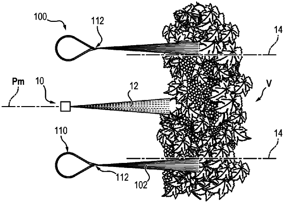
the system comprising spray nozzles for spraying a plant-protection product and air flow generator means comprising a conduit comprising two parallel rectilinear sections, the spray nozzles being placed and distributed linearly at a centre of said conduit between the two rectilinear sections, the spray nozzles being equidistantly distributed in a median longitudinal plane of said conduit,
wherein
said conduit comprises overall incurved linking ends connecting said two parallel rectilinear sections, such that the conduit has the form of an oblong ring and has an outlet in the form of an annular slit of oblong contour adapted to generate an air flow in the form of a continuous tubular air confinement curtain laterally from the spray nozzles, the air curtain enclosing the jets originating from the spray nozzles and being impassable by the plant-protection product sprayed by the spray nozzles
wherein
the conduit is formed by assembling a plurality of rectilinear segments and incurved segments,
each of the rectilinear segments and of the incurved segments being delimited on the inside by a cap covering an angular opening larger than an angle with a value of 180 degrees, the cap being extended by two overall flat facets which converge by moving away from the cap to the annular slit, according to an angle with a value about 60 degrees, in order to generate a laminar flow at the outlet of the annular slit and a turbulent flow directed to the plants to be sprayed.
|