| CPC A47L 13/142 (2013.01) [A47L 13/58 (2013.01)] |

| AS A RESULT OF REEXAMINATION, IT HAS BEEN DETERMINED THAT: |
| Claims 1 and 3 are determined to be patentable as amended. |
| Claims 2 and 5, dependent on an amended claim, are determined to be patentable. |
| Claims 4 and 6 were not reexamined. |
|
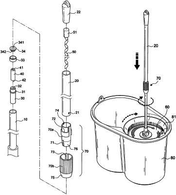
1. A mop with the function of dewatering mop yarns by twisting in a single direction via an up-and-down linear motion, comprising:
a) an internal rod;
b) an external rod having a bottom portion in a telescopic connection with a top portion of the internal rod;
c) an engaging element positioned within the opening at the top of the internal
d) a driving element formed in an elongated shape and positioned within the external rod in such a way that the driving element is moved up and down synchronically with the external rod;
e) an actuating element positioned within the engaging element for accommodating the driving element, the engaging element
f) a disc body secured to the bottom thereof and having the mop yarns secured to the disc body;
g) a locking mechanism mounted on the external rod for locking the internal rod and the external rod in place or for unlocking them in a telescopic state,
wherein the actuating element is rotated by a linear motion of the driving element when the external rod is moved up-and-down; moreover, the engaging element is driven in rotation in a single direction, thereby creating a continuous rotation of the internal rod and the disc body in the same direction by the inertia force; as a result, a centrifugal force is produced to throw away the water absorbed in the mop yarns; and
the disc body cooperates with a dewatering basket rotatable within a bucket body, and wherein the dewatering basket is synchronically driven in rotation when the disc body is rotated by the internal rod; the mop yarns of the disc body are subject to the centrifugal force for dewatering, and the water removed is received within the bucket body.
|
|
3. The mop with the function of dewatering the yarns by twisting in a single direction via an up-and-down linear motion as recited in claim 1 wherein the engaging element is positioned at the top of the internal rod and fixed by an annular element
|