| CPC H02M 7/797 (2013.01) [B60L 53/50 (2019.02); H02M 1/4216 (2013.01); H02M 3/158 (2013.01); H02M 1/0058 (2021.05)] | 20 Claims |

|
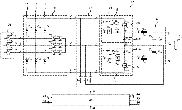
1. An electrical converter for conversion between a three-phase AC signal and a DC signal, the electrical converter comprising:
three phase terminals (A, B, C);
a first DC terminal (P) and a second DC terminal (N);
a phase selector configured to connect the three phase terminals to a first intermediate node (x), a second intermediate node (y) and a third intermediate node (z) of the electrical converter;
a first buck circuit comprising a first switch-node terminal (p) operably connected to the first DC terminal (P) and a second buck circuit comprising a second switch-node terminal (n) operably connected to the second DC terminal (N), wherein the first and the second buck circuits are connected and configured to convert a voltage at the first intermediate node (x), the second intermediate node (y), and the third intermediate node (z) to a voltage between the first and second DC terminals (P, N);
wherein the first and the second buck circuits are connected in series between the first intermediate node (x) and the second intermediate node (y) such that there is a common node (m) of the first and second buck circuits;
wherein the first and second buck circuits comprise at least one actively switchable device connected between the common node and the third intermediate node;
wherein the first buck circuit is configured to allow connecting the first switch-node terminal (p) to any one of the first intermediate node (x), the third intermediate node (z), and the common node (m); and
wherein the second buck circuit is configured to allow connecting the second switch-node terminal (n) to any one of the second intermediate node (y), the third intermediate node (z), and the common node (m).
|