| CPC H02M 3/1584 (2013.01) [H02M 1/08 (2013.01); H02M 1/0054 (2021.05)] | 19 Claims |

|
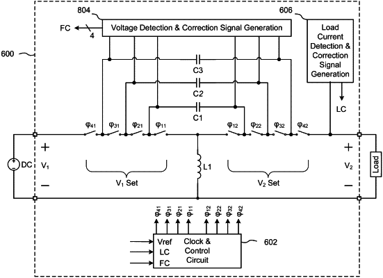
13. A multi-level DC-to-DC converter circuit for converting an input voltage to an output voltage, including:
(a) a plurality of main switches;
(b) an inductor coupled to a node within the plurality of main switches;
(c) at least one capacitor coupled to at least some of the plurality of main switches and selectively couplable through the plurality of main switches to the inductor and/or a voltage source and/or a voltage sink;
(d) a control circuit coupled to the main switches and configured to set states for the main switches;
(e) a switched resistance network, coupled to at least one capacitor and to at least one main switch; and
(f) a directional correction circuit, coupled to at least one capacitor and to the switched resistance network, and configured to sense deviations in a voltage across at least one coupled capacitor and generate corresponding directional correction signals to the switched resistance network that, alone or in combination, dynamically change a pattern of charge or discharge states for the at least one coupled capacitor to selectively steer the voltage across the at least one coupled capacitor towards a balanced voltage state.
|