US 11,881,717 B2
Pinless power coupling
Yossi Azancot, Jerusalem (IL); Amir Ben-Shalom, Modiin (IL); Oola Greenwald, Mevasseret Zion (IL); and Arik Rofe, Jerusalem (IL)
Assigned to POWERMAT TECHNOLOGIES LTD., Neve Ilan (IL)
Filed by POWERMAT TECHNOLOGIES LTD., Petah Tikva (IL)
Filed on Mar. 20, 2023, as Appl. No. 18/186,415.
Application 18/186,415 is a continuation of application No. 17/902,393, filed on Sep. 2, 2022, granted, now 11,611,240.
Application 17/902,393 is a continuation of application No. 17/467,382, filed on Sep. 6, 2021, granted, now 11,437,852, issued on Sep. 6, 2022.
Application 17/467,382 is a continuation of application No. 16/828,410, filed on Mar. 24, 2020, granted, now 11,114,895, issued on Sep. 7, 2021.
Application 16/828,410 is a continuation of application No. 15/499,335, filed on Apr. 27, 2017, abandoned.
Application 15/499,335 is a continuation of application No. 14/024,051, filed on Sep. 11, 2013, granted, now 9,666,360, issued on May 30, 2017.
Application 14/024,051 is a continuation of application No. 12/524,987, granted, now 8,629,577, issued on Jan. 14, 2014, previously published as PCT/IL2008/000124, filed on Jan. 28, 2008.
Claims priority of provisional application 61/006,488, filed on Jan. 16, 2008.
Claims priority of provisional application 60/935,694, filed on Aug. 27, 2007.
Claims priority of provisional application 60/897,868, filed on Jan. 29, 2007.
Prior Publication US 2023/0231416 A1, Jul. 20, 2023
This patent is subject to a terminal disclaimer.
Int. Cl. H02J 50/10 (2016.01); H01F 38/14 (2006.01); H02J 50/90 (2016.01); H01F 27/28 (2006.01)
CPC H02J 50/10 (2016.02) [H01F 27/2804 (2013.01); H01F 27/2885 (2013.01); H01F 38/14 (2013.01); H02J 50/90 (2016.02); H01F 2027/2809 (2013.01)] 16 Claims
OG exemplary drawing
 
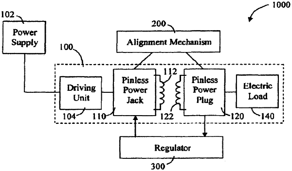
1. A pinless power plug for receiving wireless power from a pinless power jack, the pinless power plug comprising:
at least one secondary coil for inductively coupling with a primary coil, wherein the primary coil is associated with the pinless power jack, and wherein the primary coil is shielded behind an insulating layer;
an annular magnetic anchor arranged around a perimeter of the at least one secondary coil concentric and non-overlapping with the at least one secondary coil, wherein the annular magnetic anchor is configured to magnetically couple with an annular magnetic snag in the pinless power jack; and
at least one magnet spaced away from and outside of the annular magnetic anchor, wherein the at least one magnet is configured to magnetically couple with a magnet in the pinless power jack at a particular orientation or angle.