| CPC H01Q 7/06 (2013.01) [H01Q 1/40 (2013.01); H01Q 1/243 (2013.01)] | 12 Claims |

|
1. An ultra-low profile low frequency antenna comprising a magnetic core made of a soft-magnetic non-electro conductive material, the magnetic core having coil winding channels in three intersecting axial directions orthogonal to each other, defining X-axis (X), Y-axis (Y) and Z-axis (Z) orthogonal to each other wherein:
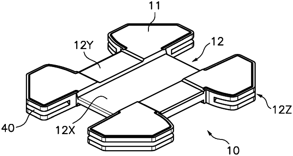
the magnetic core includes a flat central region and four corner protuberances spaced apart to each other around said central region, said corner protuberances defining therebetween a X-coil winding channel surrounding the central region around the X-axis (X), and a Y-coil winding channel surrounding the central region around the Y-axis (Y); and
a Z-coil winding channel surrounds the magnetic core around the Z-axis (Z), said Z coil winding channel being defined by a discontinuous groove confined between two parallel surfaces which are perpendicular to the Z-axis (Z) providing a rectangular cross section, said discontinuous groove including four partial grooves each included in one of the corner protuberances;
a X-coil (DX) is wound around the X-axis (X) contained within the X-coil winding channel, a Y-coil (DY) is wound around the Y-axis (Y) contained within the Y-coil winding channel, and a Z-coil (DZ) is wound around the Z-axis (Z) contained within the Z-coil winding channel; and
the X-coil (DX), the Y-coil (DY) and the Z-coil (DZ) being made of conductive wire, and each having a conductive wire entry and a conductive wire exit connected to a respective connection terminal,
the magnetic core (10) is monolithic and has a flattened drum-like shape;
the thickness of the magnetic core in the Z-axis (Z) direction is of less than 1.2 mm;
each partial groove is narrow and deep being the width of each partial groove in the Z-axis (Z) direction equal or less than 0.4 mm and being the depth of each partial groove in a radial direction perpendicular to the Z-axis (Z) direction at least two times the width thereof; and
the Z-coil (DZ) is wound within said Z-coil winding channel inserted in said narrow deep groove and extending radially from ⅓ to ⅔ of the depth of the groove and the outer edge of the Z-coil wound in the Z-coil winding channel, is at a distance of the entrance of the groove so that the parallel surfaces extent in cantilever beyond said outer edge.
|