| CPC H01F 27/2804 (2013.01) [H01F 17/0013 (2013.01); H01F 17/04 (2013.01); H01F 27/292 (2013.01); H05K 9/0083 (2013.01); H01F 2027/2809 (2013.01)] | 20 Claims |

|
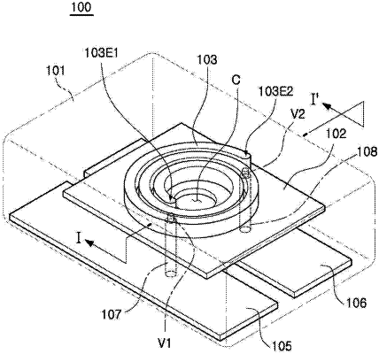
1. A coil electronic component, comprising:
a support member having a first surface and a second surface opposing each other;
a coil pattern disposed on the first surface of the support member, and including a lower surface to face the support member, an upper surface opposing the lower surface, and a side surface connecting the lower surface to the upper surface;
first and second conductive vias spaced apart from edges of the support member, penetrating the support member, and connected to one end and another end of the coil pattern, respectively;
an encapsulant encapsulating the support member and the coil pattern; and
first and second external electrodes disposed on a lower surface of the encapsulant and connected to the first and second conductive vias, respectively,
wherein the support member is disposed between the lower surface of the encapsulant and the coil pattern,
the coil pattern protrudes from the first surface of the support member, such that the upper surface of the coil pattern and a portion of the side surface of the coil pattern connected to the upper surface of the coil pattern are spaced apart from the support member, and
the encapsulant is disposed between adjacent turns of the coil pattern.
|