| CPC G01P 15/125 (2013.01) [G01P 15/0802 (2013.01); G01P 15/093 (2013.01); G01P 15/18 (2013.01)] | 15 Claims |

|
1. An acceleration sensor, comprising:
a substrate;
a sensing unit arranged on the substrate; and
a plurality of anchor blocks fixed on the substrate and located at a same level as the sensing unit, and the anchor blocks are configured to fixed the sensing unit on the substrate;
wherein the sensing unit comprises:
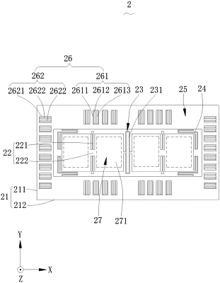
an outer coupling unit, wherein the outer coupling unit has a ring structure, and comprises two first side beams spaced apart and opposite to each other along a first direction and two second side beams spaced apart and opposite to each other along a second direction; the outer coupling unit is stacked on the substrate, and a plane where the first direction and the second direction are located is parallel to the substrate;
at least two seesaw structures, wherein the at least two seesaw structures are arranged at intervals on an inner side of the outer coupling unit, and each of the seesaw structures comprises two spaced torsion springs arranged parallel to the substrate and a connecting beam parallel to the substrate and fixed on the torsion spring; the connecting beam is perpendicular to the torsion springs, ends of the two torsion springs that are close to each other are connected to the connecting beam, and ends of the torsion springs away from each other are fixed on two of the plurality of anchor blocks and further fixed on the substrate through the two anchor blocks;
an inner coupling unit, comprising an inner coupling elastic beam, wherein the inner coupling elastic beam is located between two adjacent seesaw structures of the at least two seesaw structures, and elastically connects the two adjacent seesaw structures of the at least two seesaw structures; the inner coupling elastic beam is configured to generate a co-coupling to weaken a rotation in a surface of the seesaw structures when the seesaw structures moves along a third direction; wherein the first direction, the second direction and the third direction are perpendicular to each other;
proof mass blocks fixed on the outer coupling unit;
in-plane coupling elastic members, wherein the in-plane coupling elastic members are located at ends of the seesaw structures away from the inner coupling elastic beam and is elastically connected to the seesaw structures to the outer coupling unit, and are configured to provide a flexible support for linear movements of the proof mass blocks along the first direction and/or the second direction and co-couple movements of the seesaw structures along the third direction;
an in-plane displacement detection device arranged on the proof mass blocks, and configured to detect the linear movements of the proof mass blocks along the first direction and/or configured to detect the linear movements of the proof mass blocks along the second direction; and
a plurality of out-of-plane displacement detection devices arranged on the outer coupling unit and/or the seesaw structures and/or the inner coupling unit, and configured to detect movements of the proof mass blocks and/or the seesaw structures and/or the inner coupling unit along the third direction;
wherein the in-plane displacement detection device is a displacement-capacitance detection device, comprising a plurality of X-axis in-plane displacement detection devices configured to detect the linear movements of the proof mass blocks along the first direction, and/or a plurality of Y-axis in-plane displacement detection devices configured to detect the linear movements of the proof mass blocks along the second direction;
each of the X-axis in-plane displacement detection devices comprises a first X-axis capacitance plate located on the proof mass blocks, a second X-axis capacitance plate anchored on the substrate and configured to form a detection capacitance structure with the first X-axis capacitance plate, and a third X-axis horizontal capacitance plate anchored on the substrate, forming a detection capacitance structure with the first X-axis capacitance plate and differentially arranged with the second X-axis capacitance plate;
the first X-axis capacitance plate extends along the second direction, and the second X-axis capacitance plate and the third X-axis capacitance plate are relatively spaced along the first direction;
each of the Y-axis in-plane displacement detection devices comprises a first Y-axis capacitance plate located on the proof mass blocks, a second Y-axis capacitance plate anchored on the substrate and configured to form a detection capacitance structure with the first Y-axis capacitance plate, and a third Y-axis horizontal capacitance plate anchored on the substrate, forming a detection capacitance structure with the first Y-axis capacitance plate and differentially arranged with the second Y-axis capacitance plate; and
the first Y-axis capacitance plate extends along the first direction, and the second Y-axis capacitance plate and the third Y-axis capacitance plate are relatively spaced along the second direction.
|