| CPC F02B 77/10 (2013.01) [F01M 13/0405 (2013.01); F16K 17/0413 (2013.01); F02M 35/10262 (2013.01)] | 20 Claims |
|
1. An explosion relief valve for a crankcase, the valve comprising:
a carrier plate having an outer perimeter, a lower surface, an upper surface opposite the lower surface, and an inner circumference that defines a valve inlet extending through the carrier plate from the lower surface to the upper surface;
a cap including an outer perimeter and a lower surface;
an annular flame arrestor extending from the upper surface of the carrier plate to the lower surface of the cap, the annular flame arrestor being coaxially aligned with the carrier plate and the cap;
a gasket positioned against the upper surface of the carrier plate and around the valve inlet of the carrier plate; and
a valve plate having a perimeter, a lower surface, and an upper surface opposite the lower surface, the lower surface of the valve plate being positioned against the gasket proximate to the valve inlet such that the valve plate covers the valve inlet;
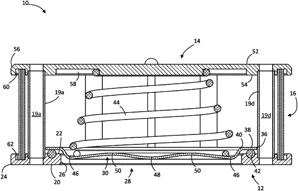
a valve spring located between the lower surface of the cap and the upper surface of the valve plate, the valve spring being compressed to bias the valve plate against the gasket;
wherein the valve plate has a central trough portion, an outer trench portion, a medial crest portion located between the outer trench portion and the central trough portion, and an outer lip portion that engages the gasket, the central trough portion being positioned lower than the medial crest portion.
|