| CPC F01N 3/2013 (2013.01) [F01N 2240/16 (2013.01); F01N 2260/20 (2013.01); F01N 2450/16 (2013.01)] | 14 Claims |

|
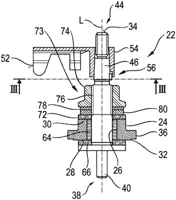
1. A connection unit for connecting an electrical supply line to an exhaust gas heater of an exhaust system of an internal combustion engine, the connection unit comprising:
a connection element defining a longitudinal axis (L) and being elongated along said longitudinal axis (L);
said connection element being electrically conductive and having first and second axial end regions;
said connection element having an exhaust gas heating connection region in said first axial end region and having a connection region for said electrical supply line in said second axial end region;
a connection element carrier having a first end face and a second end face, said first end face facing toward said first axial end region of said connection element and facing away from said second axial end face, said second end face facing toward said second axial end region of said connection element and facing away from said first axial end face, said connection element carrier defining a connection element receiving opening extending between said first end face and said second end face for accommodating said connection element therein;
said connection element having a support region lying between said first and second axial end regions;
a first insulating element arranged in said connection element receiving opening, said first insulating element being configured as an insulating sleeve surrounding said support region;
a second insulating element arranged on said first end face;
said connection element being supported axially with respect to said first end face of said connection element carrier via said second insulating element;
a third insulating element arranged on said second end face of said connection element carrier;
said connection element being supported axially with respect to said second end face of said connection element carrier via said third insulating element;
said first insulating element, said second insulating element and said third insulating element being configured as separate components; and,
an axial gap being formed between said first insulating element and at least one insulating element of said second insulating element and said third insulating element.
|