| CPC F01D 25/285 (2013.01) [F05D 2230/70 (2013.01)] | 10 Claims |

|
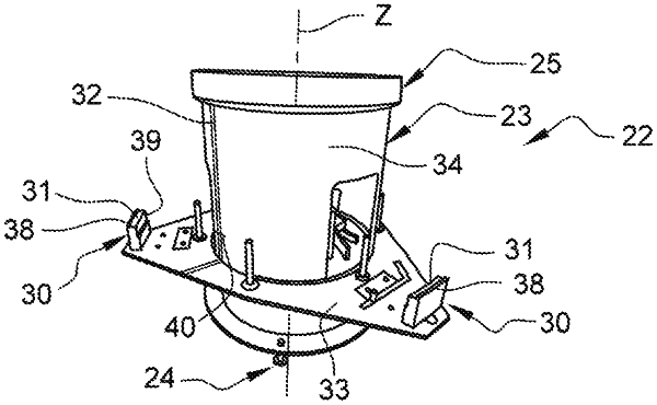
1. A tool for removing a fan disc alone from a module having a longitudinal axis of a turbomachine comprising a rotor and a stator, the rotor comprising the fan disc, a drum and an annular sealing part centered on the axis and secured to one another via a circular row of bolts each comprising a screw and a nut, each screw passing through a retaining member arranged inside the rotor, each retaining member having at least two opposing lugs arranged around a head of the screw and projecting with respect to the head, the stator being centered on the axis and surrounding the drum, the stator being longitudinally delimited by a compressor stator vanes assembly arranged opposite the fan disc, the compressor stator vanes assembly comprising an outer shell having a flange, the tool having a vertical axis comprising:
a frame comprising ground support means;
an annular plate centered on the axis and secured to the frame, this plate comprising first and second circular rows of pins as well as two holes arranged around the axis at a regular pitch, each of the two holes being arranged between the first and second rows, each of the pins being configured to bear the head of one of the screws so as not to damage the lugs of the retaining members, each of the holes being configured to receive an indexing finger of the module relative to the tool;
at least three supports distributed in a regular manner around the axis (Z) and secured to the frame, each of the supports comprising a bearing surface, the bearing surfaces being coplanar and being configured to support the flange of the compressor stator vanes assembly of the module, the three supports being vertically located below the plate;
a first visual marker arranged on the frame and configured to angularly orient the module relative to the tool.
|