| CPC B04B 11/04 (2013.01) [B04B 11/02 (2013.01); B04B 11/082 (2013.01); B04B 2005/0464 (2013.01)] | 24 Claims |

|
1. Apparatus comprising:
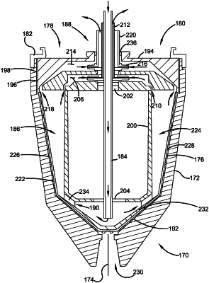
a single use structure configured for use in a centrifuge system including a multi-use rotatable centrifuge bowl, wherein the structure is configured to be removably positioned in the bowl and to separate within an interior area of the structure, cells in a cell culture batch into concentrate and centrate,
the structure in an operative position, including
an upper disc shape portion,
a lower portion,
a cylindrical core intermediate of the upper portion and the lower portion,
a separation chamber in radially surrounding relation of the core,
an outer wall, wherein the outer wall
extends in fluid tight operative relation with the upper disc shape portion and bounds the separation chamber,
extends in surrounding relation of the core, and
has an internal truncated cone shape with a smaller inside radius adjacent the lower portion,
a vertically extending feed tube,
a vertically extending centrate discharge tube,
wherein the upper disc shape portion and the outer wall are rotatable within the bowl about a vertical axis,
a centrate centripetal pump, wherein the centrate centripetal pump is
axially aligned with the core,
disposed coaxially about the feed tube,
in fluid communication with the centrate discharge tube, and
positioned in a centrate pump chamber, wherein the centrate pump chamber is in fluid communication with the separation chamber,
wherein during rotation of the bowl, the upper disc shape portion and the outer wall rotate relative to each of the feed tube, the centrate discharge tube and the centrate centripetal pump.
|