US 11,877,742 B2
Adjustable compression staple and method for stapling with adjustable compression
Kevin W. Smith, Coral Gables, FL (US); Matthew A. Palmer, Miami, FL (US); Korey Kline, Miami, FL (US); and Derek Dee Deville, Coral Gables, FL (US)
Assigned to Cilag GmbH International, Zug (CH)
Filed by Cilag GmbH International, Zug (CH)
Filed on Jan. 9, 2020, as Appl. No. 16/738,771.
Application 16/738,771 is a division of application No. 15/614,666, filed on Jun. 6, 2017, granted, now 10,568,620.
Application 15/614,666 is a division of application No. 14/164,748, filed on Jan. 27, 2014, granted, now 9,700,306, issued on Jul. 11, 2017.
Application 14/164,748 is a division of application No. 13/222,758, filed on Aug. 31, 2011, granted, now 8,679,156, issued on Mar. 25, 2014.
Application 13/222,758 is a division of application No. 11/971,998, filed on Jan. 10, 2008, granted, now 8,679,154, issued on Mar. 25, 2014.
Application 14/164,748 is a division of application No. 11/971,998, filed on Jan. 10, 2008, granted, now 8,679,154, issued on Mar. 25, 2014.
Claims priority of provisional application 60/880,146, filed on Jan. 12, 2007.
Prior Publication US 2020/0146675 A1, May 14, 2020
This patent is subject to a terminal disclaimer.
Int. Cl. A61B 17/064 (2006.01); F16B 15/00 (2006.01)
CPC A61B 17/0644 (2013.01) [A61B 17/064 (2013.01); F16B 15/0015 (2013.01)] 20 Claims
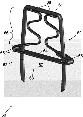
OG exemplary drawing
 
1. A compression-self-adjusting staple, comprising:
a substantially U-shaped staple having:
a bridge;
two legs extending from the bridge at an angle thereto; and
a compression device:
at least partly disposed between the legs; and
having a bias portion with:
a compression surface movably disposed between the legs; and
a compression resistor:
 connected to the bridge and to the compression surface; and
 formed into a plurality of bends that resist movement of the compression surface towards the bridge with a pre-set compressive force.