| CPC H02M 3/158 (2013.01) [H02M 3/01 (2021.05)] | 22 Claims |

|
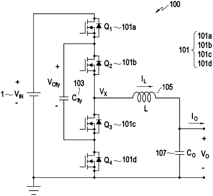
1. A direct current (DC)/DC converter comprising:
multiple switches;
a capacitor;
an inductor; and
at least one processor,
wherein the multiple switches comprise:
a first switch including a first end connected to an input power source and being configured to connect a first end of the capacitor to the input power source when the first switch is in an on state,
a second switch including a first end connected to a second end of the first switch and being configured to connect the first end of the capacitor to a first end of the inductor when the second switch is in the on state,
a third switch including a first end connected to a second end of the second switch and being configured to connect a second end of the capacitor to the first end of the inductor when the third switch is in the on state, and
a fourth switch including a first end connected to a second end of the third switch and being configured to connect the second end of the capacitor to ground when the fourth switch is in the on state,
wherein the first end of the capacitor is connected to the second end of the first switch and the first end of the second switch, and the second end of the capacitor is connected to the second end of the third switch and the first end of the fourth switch,
wherein the first end of the inductor is connected to the second end of the second switch and the first end of the third switch, and a second end of the inductor is connected to an output end of the DC/DC converter,
wherein the at least one processor is configured to:
compare an output voltage of the DC/DC converter with a first threshold voltage, and
compare current output from the inductor with a first threshold current, and
wherein, when the output voltage of the DC/DC converter is less than the first threshold voltage, the at least one processor is further configured to:
control an on/off state of the multiple switches so as to increase the current output from the inductor based on the current output from the inductor being less than the first threshold voltage; and
control the second switch and the fourth switch to be in the on state or control the first switch and the third switch be in the on state to allow the first end or the second end of the capacitor to be connected to the first end of the inductor based on the current output from the inductor being greater than or equal to the first threshold current.
|