| CPC G01N 27/327 (2013.01) [G01N 33/53 (2013.01); G01N 33/6803 (2013.01); B01D 53/326 (2013.01); B01D 2313/18 (2013.01)] | 14 Claims |

|
1. A system for detecting an analyte in a sample, the system comprising:
at least one assay reaction chamber;
a potentiostat;
a counter electrode; and
a reference electrode;
wherein the potentiostat is in electronic communication with the counter electrode, the reference electrode, and the at least one assay reaction chamber;
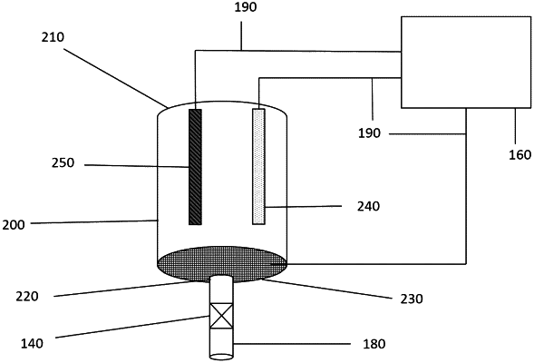
each assay reaction chamber comprising: a porous working electrode having a plurality of analyte capturing molecules specific for the analyte being bound on the surface of the porous working electrode to provide a capture surface on the porous working electrode, through which the sample flows, an ingress opening through which the sample is capable of entering the assay reaction chamber, and an egress opening through which the sample is capable of exiting the assay reaction chamber; the porous working electrode having a porosity ranging from approximately 25% to approximately 90% and a surface area to volume ratio ranging from approximately 0.25 m2 g and approximately 10 m2/g, and being positioned within a lower portion of the assay reaction chamber;
wherein the porous working electrode having the analyte capturing molecules is located on a bottom of the assay reaction chamber, the porous working electrode spans the assay reaction chamber and surrounds the egress opening to form a barrier between the ingress opening and the egress opening such that the sample must flow through the barrier to reach the egress opening;
wherein the reference electrode and the counter electrode are on the inside wall of each of the assay reaction chamber and are situated above the porous working electrode;
and free within the assay reaction chamber a plurality of analyte-detector molecule comprising an enzyme label and a substrate for the enzyme label,
wherein the system is structured so that as the sample flows through pores of the porous working electrode, the analyte-capturing molecules specifically bind to any analyte present in the sample and generate an electric current when the plurality of analyte-detector molecules and the substrate are added to the reaction chamber; the electric current is being generated from the enzymatic reaction of the enzyme on the substrate from the analyte detector molecules that is bound to the analyte captured by the analyte-capturing molecule;
the electric current is transmitted to the potentiostat, the presence and quantity of the electric current indicating a presence of the analyte in the sample.
|