| CPC F16K 11/06 (2013.01) [F16K 31/12 (2013.01); H02K 26/00 (2013.01)] | 11 Claims |

|
1. A pneumatic proportional valve with high frequency response and low power consumption, comprising a torque motor and a pneumatic rotary valve; wherein
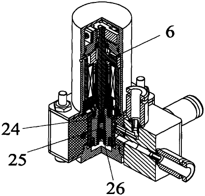
the torque motor has a single coil structure and comprises permanent magnets, magnetically permeable yokes, an upper armature, a lower armature, an upper skeleton, a skeleton column, a lower skeleton, an exciting coil, a coil skeleton, a spring support, a spring plate and load springs;
the upper skeleton and the lower skeleton are respectively provided with a blind hole, and two ends of the skeleton column are respectively inserted into the blind holes of the upper skeleton and the lower skeleton; the exciting coil is wound on the coil skeleton, and the skeleton column runs through a through hole in the middle of the coil skeleton and is sandwiched between the upper skeleton and the lower skeleton;
the upper armature comprises armature arms and a magnetically permeable column in the middle, the magnetically permeable column running through a through hole in the middle of the skeleton column, and the armature arms being arranged in a groove of the upper skeleton; the lower armature is arranged in a groove of the lower skeleton and connected to a lower end of the magnetically permeable column of the upper armature through an interference fit, and the lower end of the magnetically permeable column is also connected to the lower skeleton through a first bearing;
four magnetically permeable yokes are attached to a periphery of the exciting coil, each of the magnetically permeable yokes being in a shape of a cylindrical sector as a whole, and two side surfaces perpendicular to each other being closely attached to outer wall surfaces of the grooves of the upper skeleton and the lower skeleton respectively; four permanent magnets are respectively sandwiched among the four magnetically permeable yokes; the armature arms of the upper armature and the armature arms of the lower armature are vertically staggered up and down, and form eight working air gaps with the four magnetically permeable yokes;
the spring support is mounted on an upper end surface of the upper skeleton, a second bearing is provided on the spring support and configured to support an upper end of the magnetically permeable column, and a middle of the spring plate is provided with a semi-circular through hole that is fitted with a semi-circular shaft on the upper end of the magnetically permeable column and fixed by means of a stop screw;
four load springs are respectively arranged on a periphery of the spring plate, and an amount of compression of the load springs on two ends of the spring plate is adjusted, thereby adjusting an initial rotation angle of the armatures;
the pneumatic rotary valve comprises a valve body, a valve sleeve, a valve core, a wedge, an air valve connecting piece and pneumatic connectors;
the valve body and the valve sleeve are in an interference fit, and the valve core and the valve sleeve are in a clearance seal and connected through a bearing pack;
a middle of the valve core is provided with a semi-circular straight through hole and a threaded blind hole, and the wedge is arranged in the blind hole of the valve core, a flat side surface of the wedge being closely attached to a flat side surface of the semi-circular straight through hole of the valve core, and an inclined side surface of the wedge being closely attached to an inclined surface on the lower end of the magnetically permeable column; transmission between the torque motor and the valve core is realized by means of the inclined surface and the flat side surface of the wedge; and
a flow channel in the valve body is aligned with and attached to a flow channel in the air valve connecting piece, threaded ends of the pneumatic connectors are screwed into four threaded holes of the air valve connecting piece, and quick plug ends are connected to a pneumatic system to be controlled.
|