| CPC B61G 5/10 (2013.01) [B61G 7/14 (2013.01); H01H 9/30 (2013.01); B61L 15/0036 (2013.01)] | 10 Claims |

|
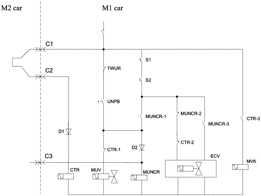
1. An intermediate car electric coupler control circuit for a subway vehicle, comprising
a coupling state relay (CTR) provided in series in a coupler coupling line having a first full-automatic coupler electric contact (C1) and a second full-automatic coupler electric contact (C2);
a first power supply circuit for a decoupling electromagnetic valve (MUV), comprising a normally-closed contact (TWUR) of a wake-up relay, a decoupling button switch (UNPB), and a first normally-closed contact (CTR-1) of the coupling state relay, wherein the normally-closed contact (TWUR) of the wake-up relay, the decoupling button switch (UNPB) and the first normally-closed contact (CTR-1) of the coupling state relay are sequentially connected in series between a train power supply and the decoupling electromagnetic valve (MUV);
a second power supply circuit for an electric coupler control relay (MUNCR), comprising mechanical coupler position switches (S1, S2) and a first normally-open contact (MUNCR-1) of the electric coupler control relay wherein the mechanical coupler position switches (S1, S2) and the first normally-open contact (MUNCR-1) are sequentially connected in series between the train power supply and the electric coupler control relay (MUNCR), a high-potential terminal of the electric coupler control relay (MUNCR) is connected to a low-potential terminal of the decoupling button switch (UNPB) through a wire;
a third power supply circuit for an air path and an electric coupler module control electromagnetic valve (ECV), comprising a first power supply electronic circuit and a second power supply electronic circuit, wherein the first power supply electronic circuit and the second power supply electronic circuit are connected in parallel to low-potential terminals of the mechanical coupler position switches (S1, S2), the first power supply electronic circuit comprises a normally-closed contact (MUNCR-2) of the electric coupler control relay and a second normally-closed contact (CTR-2) of the coupling state relay connected in series; the second power supply electronic circuit comprises a second normally-open contact (MUNCR-3) of the electric coupler control relay; and
a fourth power supply circuit for a bus control contactor (MVK), comprising a third normally-open contact (CTR-3) of the coupling state relay connected in series between the train power supply and the bus control contactor (MVK).
|