| CPC B05C 5/022 (2013.01) [B05C 13/02 (2013.01); B05C 13/025 (2013.01); B05C 5/027 (2013.01)] | 8 Claims |

|
1. A sealant liner apparatus comprising:
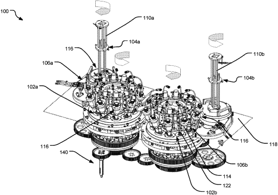
two motor driven turret systems, including a first turret system that rotates in a direction that is opposite a direction that a second turret system rotates;
two main drive motors to drive each of the two motor driven turret systems, wherein a first main drive motor is configured to drive the first turret system and a second main drive motor is configured to drive the second turret system;
a plurality of workstations located on each of the two motor driven turret systems spaced apart and extending outwardly from a circumference thereof, each workstation of the plurality of workstations adapted for receiving an individual can end;
two downstackers, each downstacker of the two downstackers located proximate to a turret system of the two motor driven turret systems to feed the individual can end to an individual workstation of the plurality of workstations and proximate to an exit chute that discharges the individual can end from the turret system of the two motor driven turret systems; and
at least one sealant applicator mounted on each individual workstation of the plurality of workstations, the at least one sealant applicator electronically controlled to apply a sealant on the individual can end, wherein the exit chute comprises a first exit chute and the sealant liner apparatus further comprises a second exit chute, the first turret system configured to discharge the individual can end to the first exit chute and the second turret system configured to discharge the individual can end to the second exit chute, and wherein the first exit chute and the second exit chute are both positioned on a first side of the sealant liner apparatus and discharge the individual can end to the first side of the sealant liner apparatus to a single discharge conveyor.
|