| CPC A63H 33/002 (2013.01) [A63H 33/22 (2013.01)] | 6 Claims |
|
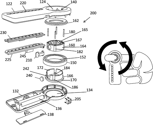
1. A finger mounted spinning device comprising:
a housing body defined to have an elongated body extending oppositely to an opening positioned about one end of the housing body;
a finger ring assembly positioned within the opening of the housing body, the finger ring assembly having an inner ring and outer ring, and wherein the finger ring assembly is configured to cause rotation of the outer ring independently of the inner ring;
an aperture through the inner ring sized to receive a finger from a person's hand;
an annular finger gripping member positioned within the aperture of the annular finger ring hub to grip the finger from a person's hand;
a weight is positioned elongated body, and
wherein the finger ring assembly is further defined as including a bearing casing that is secured about the opening positioned about one end of the housing body, and the bearing casing defines the inner ring and outer ring of the finger ring assembly, and
an annular finger ring hub secured within the inner ring of the bearing casing, the annular finger ring hub having a top ring hub, a middle ring hub and a bottom ring hub, wherein the middle ring hub being configured to define the aperture that receives the finger from the person's hand, and wherein the bottom ring hub being configured to include an outward extending shoulder and an upwardly extending skirt configured to capture the middle ring hub within the skirt and allow the bearing casing to rest on the outward extending shoulder, and
support pins positioned through shafts that are positioned around an outside of the middle ring hub, the support pins sitting in holes defined along the bottom ring hub and further secured to the top ring hub.
|