| CPC A47B 88/473 (2017.01) [A47B 88/49 (2017.01); F16C 29/02 (2013.01)] | 7 Claims |
|
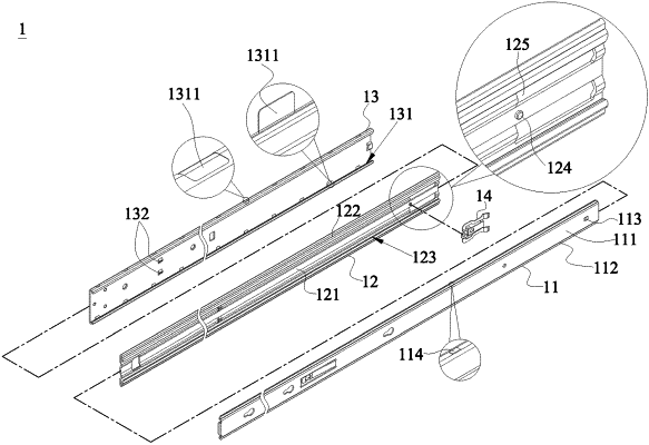
1. A frictional slide rail with synchronous middle and inner rails and lockable middle and outer rails, comprising:
an inner rail, bent to form a first protrusion at central part thereof, and having a first wing formed on both sides of the inner rail;
a middle rail, bent to form a second protrusion at central part thereof, and having a second wing and a first slide groove formed on both sides of the middle rail respectively, and provided for movably accommodating the first wings of the inner rail in the first slide grooves respectively, such that the inner rail forms a frictional sliding connection in the middle rail;
an outer rail, bent to form a second slide groove on both sides thereof, and provided for movably accommodating the second wings of the middle rail, such that the middle rail forms a frictional sliding connection in the outer rail, and the second slide grooves comprise a plurality of micro top bumps formed therein and configured to be corresponsive to the second wings, for reducing frictional area during sliding; and
a synchronous locking spring plate, which is a rectangular frame-structured elastic member formed by stamping a metal sheet, and an end of the synchronous locking spring plate having a fixing part to be installed on the middle rail, and another end of the synchronous locking spring plate having a moving plate with an inner and middle rails locking part and a middle and outer rails locking part disposed on the moving plate, and a pair of trigger parts are extended from an end of the synchronous locking spring plate opposite to the fixing part; such that when the inner rail is pulled outward, the inner and middle rails locking part and the inner rail are engaged with each other to define a synchronization, and the middle rail is pulled outward with the inner rail, and when the middle rail is pushed inward, the middle and outer rails locking part and the outer rail are locked, wherein
the middle rail comprises a positioning column corresponding to the synchronous locking spring plate, and a pair of through holes formed on a side of the positioning column, and the pair of trigger parts after installation are disposed in the pair of through holes to define a moving state.
|