| CPC G09G 3/2092 (2013.01) [G09G 3/3208 (2013.01); G09G 3/3266 (2013.01); G09G 3/3275 (2013.01); G09G 3/3291 (2013.01); G09G 3/3685 (2013.01); G09G 2300/0426 (2013.01); G09G 2310/0272 (2013.01); G09G 2310/0275 (2013.01); G09G 2380/02 (2013.01)] | 19 Claims |

|
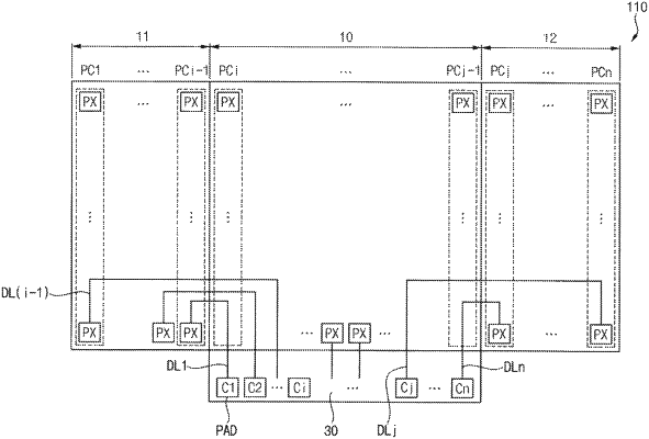
1. A display device, which is a slidable display device, comprising:
a display panel including:
a first display area,
a second display area that is configured to be taken in and out of the display device,
a pad area located on a first side of the first display area,
a plurality of pixels disposed in the first and second display areas, and configured to operate in one of a first mode in which an image is displayed in the first display area and a second mode in which an image is displayed in the first and second display areas; and
a data driver configured to:
receive input image data;
generate a plurality of data voltages based on pixel data of the input image data,
output the plurality of data voltages to the plurality of pixels, and
control an order of the plurality of data voltages output in the second mode,
wherein the data driver includes:
an opposite direction channel selector configured to:
receive a mode selection signal representing information on one of the first mode and the second mode without receiving the input image data,
select a range of pixels in which the order of the plurality of data voltages is to be changed in an opposite direction among the plurality of pixels based on the mode selection signal, and
generate an output signal representing the range of the pixels in which the order of the plurality of data voltages is to be changed in the opposite direction;
a channel direction controller connected to the opposite direction channel selector and configured to:
receive the output signal from the opposite direction channel selector, and
generate a channel direction control signal representing an order of all of the plurality of data voltages based on the output signal;
a shift register connected to the channel direction controller and generating a sampling signal based on the channel direction control signal;
a data sampling latch connected to the shift register, wherein the data sampling latch samples the input image data based on the sampling signal; and
a buffer connected to the data sampling latch and outputting the sampled input image data as the plurality of data voltages to the plurality of pixels.
|