| CPC G02B 6/3885 (2013.01) [G02B 6/32 (2013.01); G02B 6/383 (2013.01); G02B 6/3839 (2013.01); G02B 6/3887 (2013.01); G02B 6/3888 (2021.05); G02B 6/38875 (2021.05)] | 8 Claims |

|
1. A method of making an optical cable subassembly comprising:
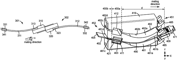
attaching one or more optical waveguides at a first attachment area of a light coupling unit, the first attachment area configured for receiving and permanently attaching to the optical waveguides; and
attaching the optical waveguides to a cable retainer comprising a second attachment area for receiving and attaching to the optical waveguides, a length of the optical waveguides between the first attachment area and the second attachment area configured to allow a bend in the optical waveguides that provides a predetermined mating spring force at a predetermined angle of the light coupling unit;
wherein the light coupling unit comprises a top major surface comprising the first attachment area opposite a bottom major mating surface, the optical waveguides permanently attached to the first attachment area, the bottom major mating surface configured to slidably contact a corresponding mating surface of a mating light coupling unit, wherein the light coupling unit redirects light received from the optical waveguides from a first direction substantially parallel to the top major surface to a different, second direction such that the light exits the light coupling unit through the bottom major mating surface, and wherein, when mated with the corresponding mating light coupling unit, the light coupling unit is oriented at a predetermined angle with respect to a mating direction and the optical waveguides are bent such that at least a portion of the bent optical waveguides is floating unsupported by any physical surface.
|