| CPC G01R 19/10 (2013.01) [H03H 7/24 (2013.01)] | 20 Claims |

|
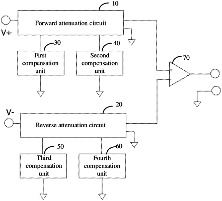
1. An attenuator, comprising a forward attenuation circuit and a reverse attenuation circuit which are symmetrical with each other, a first compensation unit and a third compensation unit which are symmetrical with each other, a second compensation unit and a fourth compensation unit which are symmetrical with each other, and a differential amplifier;
a first end of the forward attenuation circuit is connected with a positive polarity of a signal to be tested, and a second end is connected with a non-inverting input of the differential amplifier, a third end is connected with a first end of the first compensation unit, and a fourth end is connected with a first end of the second compensation unit;
a first end of the reverse attenuation circuit is connected with a negative polarity of a signal to be tested, and a second end is connected with an inverting input of the differential amplifier, a third end is connected with a first end of the third compensation unit, and a fourth end is connected with a first end of the fourth compensation unit;
a fifth end of the forward attenuation circuit and a fifth end of the reverse attenuation circuit are commonly connected to a floating output;
second ends of the first compensation unit, the second compensation unit, the third compensation unit and the fourth compensation unit are respectively connected to a floating output;
the forward attenuation circuit is used to attenuate a positive-going signal to be tested, and adjust the frequency characteristics of a preset frequency point through the first compensation unit and the second compensation unit;
the reverse attenuation circuit is used to attenuate a negative-going signal to be tested, and adjust the frequency characteristics of a preset frequency point through the third compensation unit and the fourth compensation unit;
the differential amplifier is used for receiving the positive-going signal to be tested attenuated by the forward attenuation circuit and the negative-going signal to be tested attenuated by the reverse attenuation circuit, and amplifying and outputting a difference between the attenuated positive-going signal to be tested and negative-going signal to be tested according to a preset gain.
|