| CPC G01C 19/722 (2013.01) [G02B 27/283 (2013.01)] | 10 Claims |

|
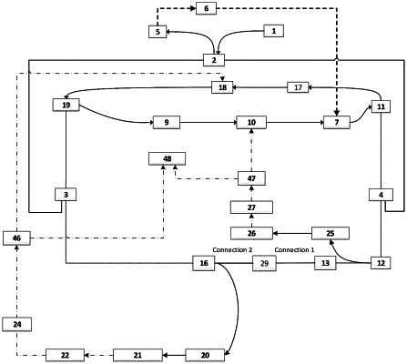
1. A bidirectional microwave-over-fiber resonant system based on a circulator structure, comprising a broadband spectrum light source (1), a 50:50 coupler (2), a first wavelength division multiplexer (3), a second wavelength division multiplexer (4), a low speed photoelectric converter (5), an interferometer controller (6), a cavity length compensation adjuster (7), a first optical amplifier (9), a first photoelectric intensity modulator (10), a first optical circulator (11), a first optical coupler (12), a narrowband bidirectional optical filter (13), a second optical coupler (16), a second optical amplifier (17), a second photoelectric intensity modulator (18), a second optical circulator (19), a first regenerative cavity cavity-length adjuster (20), a first high speed photoelectric detector (21), a first microwave filtering and amplifying unit (22), a first microwave power divider (24), a second regenerative cavity cavity-length adjuster (25), a second high speed photoelectric detector (26), a second microwave filtering and amplifying unit (27), a sensing ring interferometer structure (29), a second microwave power divider (46), a third microwave power divider (47), and a difference frequency detection unit (48);
wherein the first optical amplifier (9), the first photoelectric intensity modulator (10), the cavity length compensation adjuster (7), the first optical circulator (11), the second wavelength division multiplexer (4), the first optical coupler (12), the narrowband bidirectional optical filter (13), the sensing ring interferometer structure (29), the second optical coupler (16), the first wavelength division multiplexer (3) and the second optical circulator (19) are connected in sequence to form a clockwise ring resonant cavity; resonant light in a clockwise direction passes sequentially through the first optical coupler (12), the second regenerative cavity cavity-length adjuster (25), the second high speed photoelectric detector (26), the second microwave filtering and amplifying unit (27), and the third microwave power divider (47) to be fed back and modulated by the first photoelectric intensity modulator (10), so as to constitute a clockwise regenerative mode-locked structure; an electric signal generated by the clockwise regenerative mode-locked structure is input into the difference frequency detection unit (48) through the third microwave power divider (47);
wherein the second optical amplifier (17), the second photoelectric intensity modulator (18), the second optical circulator (19), the first wavelength division multiplexer (3), the second optical coupler (16), the sensing ring interferometer structure (29), the narrowband bidirectional optical filter (13), the first optical coupler (12), the second wavelength division multiplexer (4) and the first optical circulator (11) are connected in sequence to form a counterclockwise ring resonant cavity; resonant light in a counterclockwise direction passes sequentially through the second optical coupler (16), the first regenerative cavity cavity-length adjuster (20), the first high speed photoelectric detector (21), the first microwave filtering and amplifying unit (22), the first microwave power divider (24), and the second microwave power divider (46) to be fed back and modulated by the second photoelectric intensity modulator (18), so as to constitute a counterclockwise regenerative mode-locked structure; an electric signal generated by the counterclockwise regenerative mode-locked structure is input into the difference frequency detection unit (48) via the second microwave power divider (46);
wherein the broadband spectrum light source (1), the 50:50 coupler (2), the first wavelength division multiplexer (3), the second wavelength division multiplexer (4), the low speed photoelectric converter (5), the interferometer controller (6) and the cavity length compensation adjuster (7) constitute a reciprocity error compensation broadband spectrum optical interferometer with double loops in clockwise and counterclockwise directions; light emitted by the broadband spectrum light source (1) is divided into two arms via the 50:50 coupler (2), wherein a first arm passes in sequence through the second wavelength division multiplexer (4), the first optical circulator (11), the second optical amplifier (17), the second photoelectric intensity modulator (18), the second optical circulator (19), the first wavelength division multiplexer (3), the 50:50 coupler (2) to enter the low speed photoelectric converter (5); a second arm passes in sequence through the first wavelength division multiplexer (3), a second optical circulator (19), a first optical amplifier (9), a first photoelectric intensity modulator (10), the cavity length compensation adjuster (7), the first optical circulator (11), the second wavelength division multiplexer (4), the 50:50 coupler (2) to enter the low speed photoelectric converter (5); a detection signal of the low speed photoelectric converter (5) passes through the interferometer controller (6) and is output to control the cavity length compensation adjuster (7) to achieve a same optical path in both arms of the broadband spectrum optical interferometer and eliminate non-reciprocal errors caused by non-bidirectional devices on both arms; the light emitted by the broadband spectrum light source (1) does not interfere with the resonant light in the clockwise direction and the counterclockwise direction;
the sensing ring interferometer structure (29) comprises a first orthogonal polarization state adjusting unit (37), a polarization beam splitter (38), a fiber sensing ring (39) and a second orthogonal polarization state adjusting unit (40);
the resonant light in the clockwise direction passes through the first orthogonal polarization state adjustment unit (37) to adjust a double-peaked spectral signal of the narrowband bidirectional optical filter (13) to two paths of signals with perpendicular polarization states; and the two paths of signals enter the fiber sensing ring (39) via the polarization beam splitter (38), and pass through the polarization beam splitter (38) and the second orthogonal polarization state adjustment unit (40) to adjust the polarization states back to an initial state;
the resonant light in the counterclockwise direction passes through the second orthogonal polarization state adjustment unit (40) to adjust the double-peaked spectral signal of the narrowband bidirectional optical filter (13) to two paths of signals with perpendicular polarization states; and the two paths of signals enter the fiber sensing ring (39) via the polarization beam splitter (38), and pass through the polarization beam splitter (38) and the first orthogonal polarization state adjustment unit (37) to adjust the polarization states back to an initial state.
|