| CPC F41G 1/473 (2013.01) [F41G 3/065 (2013.01); G01S 17/08 (2013.01)] | 17 Claims |

|
1. A rangefinder, comprising:
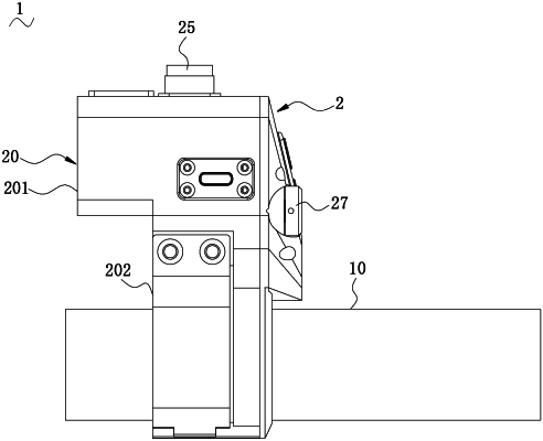
a housing detachably mounted and fixed on a sighting telescope;
a power supply, a control module, a laser ranging module, a visible laser indicator, a display module and an optical visibility adjustment system which are accommodated in the housing, wherein the power supply is electrically connected with the control module, the laser ranging module and the display module are electrically connected with the control module, an optical path of the laser ranging module is coaxial with an optical path of the visible laser indicator, the visible laser indicator is used for a position indication when a ranging and aiming position of the laser ranging module coincides with a center of a reticle of the sighting telescope, an image shown by the display module is adjusted by the optical visibility adjustment system to meet observation habits of different users and make a ranging data visible in an eyepiece field of the sighting telescope, the image displayed by the display module shows ranging and related information of the laser ranging module;
wherein the display module and the optical visibility adjustment system constitute a ranging data display system, part of the optical visibility adjustment system is movably arranged inside the housing through an adjusting element, so that an optical visibility of the ranging data display system is adjusted to be the same as an optical visibility of the sighting telescope;
wherein the optical visibility adjustment system comprises multiple mirrors and multiple convex lenses, part of the mirrors is movably set inside the housing through the adjusting element, the housing is provided with a visibility adjusting knob which is connected to the adjusting element to drive the adjusting element to move relative to the housing; and
wherein the adjusting element comprises a screw and a visibility adjusting seat located within the housing, the screw is rotationally connected to the housing, the visibility adjusting seat slidably fits with the housing, the visibility adjusting seat is screwed and installed on the screw, and the visibility adjusting knob is connected to one end of the screw, some mirrors in the optical visibility adjustment system are fixed on the visibility adjusting seat, when the visibility adjusting knob is turned, the screw drives the visibility adjusting seat to move forward and backward along the housing.
|