| CPC F25B 41/385 (2021.01) [F25B 5/04 (2013.01); F25B 6/04 (2013.01); F25B 41/22 (2021.01); F25B 49/02 (2013.01); F25B 2600/2505 (2013.01); F25B 2700/2117 (2013.01)] | 18 Claims |

|
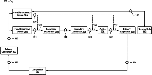
1. A Heating, Ventilation, and Air Conditioning (HVAC) system, comprising:
a condenser configured to:
receive a refrigerant in a gaseous state;
condense the refrigerant from the gaseous state into a liquid state; and
output a first condensed refrigerant in the liquid state;
a fixed expansion device fluidly coupled to the condenser, the fixed expansion device comprising a tubular structure with an opening that is configured to:
receive the first condensed refrigerant from the condenser;
output a first portion of the first condensed refrigerant at a fixed flow rate, wherein the fixed flow rate is proportional to a diameter of the opening of the tubular structure;
a sensing bulb comprising:
a hollow chamber; and
a capillary tube fluidly coupled to the hollow chamber; and
wherein the sensing bulb is configured to:
sense a temperature of a primary evaporator; and
output a fluid from the hollow chamber via the capillary tube based on the sensed temperature of the primary evaporator;
and
a variable expansion device fluidly coupled to the condenser, wherein
the variable expansion device comprises:
a flexible diaphragm fluidly coupled to the capillary tube of the sensing bulb configured to:
receive the fluid from the sensing bulb; and
apply a first force to a pin based on the received fluid from the sensing bulb;
the pin operably configured to apply a second force to a valve based on the first force, wherein the size of the pin is proportional to a ratio between a maximum variable flow rate of the variable expansion device and a total flow rate that is equal to the fixed flow rate plus the maximum variable flow rate of the variable expansion device; and
the valve is fluidly coupled to the condenser and configured to:
receive the first condensed refrigerant from the condenser;
output a second portion of the first condensed refrigerant at a variable flow rate, wherein the variable flow rate is proportional to the sensed temperature of the evaporator.
|
|
11. A method for operating a Heating, Ventilation, and Air Conditioning (HVAC) system, comprising:
receiving, at a fixed expansion device, a refrigerant from a condenser;
receiving, at a variable expansion device, the refrigerant from the condenser;
outputting, by the fixed expansion device, a first portion of the refrigerant to a first downstream HVAC component at a fixed flow rate;
sensing, by a sensing bulb, a temperature of a primary evaporator;
applying a first force to a pin of the variable expansion device based on the sensed temperature, wherein:
applying the first force to the pin repositions the pin within the variable expansion device; and
the size of the pin is proportional to a ratio between a maximum variable flow rate of the variable expansion device and a total flow rate that is equal to the fixed flow rate plus the maximum variable flow rate of the variable expansion device;
applying a second force to a valve of the variable expansion device based on the first force; and
outputting, by the valve of the variable expansion device, a second portion of the refrigerant to a second downstream HVAC component at a variable flow rate based on the second force.
|
|
18. A Heating, Ventilation, and Air Conditioning (HVAC) system, comprising:
an evaporator configured to:
receive a refrigerant in a liquid state;
evaporate the refrigerant into a gaseous state; and
output the refrigerant in the gaseous state;
a compressor fluidly coupled to the evaporator, configured to:
receive the refrigerant in the gaseous state;
compress the refrigerant; and
output the compressed refrigerant in the gaseous state;
a condenser fluidly coupled to the compressor, configured to:
receive the compressed refrigerant from the compressor;
condense the compressed refrigerant from the gaseous state into the liquid state; and
output the condensed refrigerant in the liquid state;
a fixed expansion device fluidly coupled to the condenser, comprising a tubular structure with an opening that is configured to:
receive the condensed refrigerant from the condenser;
output a first portion of the condensed refrigerant at a fixed flow rate, wherein the fixed flow rate is proportional to a diameter of the opening of the tubular structure;
a sensing bulb comprising:
a hollow chamber; and
a capillary tube fluidly coupled to the hollow chamber; and
wherein the sensing bulb is configured to:
sense a temperature of the evaporator; and
output a fluid from the hollow chamber via the capillary tube based on the sensed temperature of the evaporator;
and
a variable expansion device fluidly coupled to the condenser, wherein:
the variable expansion device is configured to:
receive the condensed refrigerant from the condenser;
output a second portion of the condensed refrigerant at a variable flow rate, wherein the variable flow rate is proportional to the sensed temperature of the evaporator; and
the variable expansion device comprises:
a flexible diaphragm fluidly coupled to the capillary tube of the sensing bulb, configured to:
receive the fluid from the sensing bulb; and
apply a first force to a pin based on the received fluid from the sensing bulb;
the pin operably configured to apply a second force to a valve based on the first force, wherein the size of the pin is proportional to a ratio between a maximum variable flow rate of the variable expansion device and a total flow rate that is equal to the fixed flow rate plus the maximum variable flow rate of the variable expansion device; and
the valve fluidly coupled to the condenser and configured to output the second portion of the condensed refrigerant.
|