| CPC F16H 48/40 (2013.01) [F16H 55/17 (2013.01); F16H 48/08 (2013.01)] | 8 Claims |

|
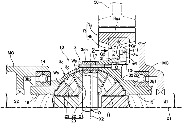
1. A power transmission device comprising a transmission member that has a radially outward facing flange portion on an outer periphery thereof and is rotatable, and a ring gear that has on an inner periphery thereof a hub portion surrounding the flange portion, an outer peripheral face of the flange portion having at least a first outer peripheral part that extends further inward in an axial direction than a side face, on one side in the axial direction, of the flange portion and has fitted and welded thereto an inner peripheral face of the hub portion, and a positioning outer peripheral part with which a positioning projecting part projectingly provided on an inner peripheral face of the hub portion is engaged further on the other side in the axial direction than the first outer peripheral part,
wherein the positioning outer peripheral part has at least a radial direction positioning face that has fitted or press fitted thereto an inner peripheral face of the positioning projecting part so as to position the hub portion in a radial direction with respect to the flange portion, and an axial direction positioning face against which a side face, on the first outer peripheral part side, of the positioning projecting part abuts so as to position the hub portion in the axial direction with respect to the flange portion,
a first annular recess part is provided in the positioning outer peripheral part so as to be recessed at least further toward a weld portion side in the axial direction than the axial direction positioning face, the first annular recess part alleviating stress caused by a pushing load via which the positioning projecting part pushes the radial direction positioning face due to the hub portion receiving a tensile force inward in the radial direction accompanying thermal shrinkage of the weld portion between the first outer peripheral part and the hub portion, and residual stress produced in an axially inner end portion of the weld portion in relation to the hub portion receiving the tensile force accompanying the thermal shrinkage can be alleviated by the first annular recess part reducing the stress due to the pushing load.
|