| CPC F16F 15/3153 (2013.01) [F16F 15/121 (2013.01); F16F 2222/08 (2013.01); F16F 2230/36 (2013.01); F16F 2232/02 (2013.01); F16F 2236/08 (2013.01)] | 8 Claims |

|
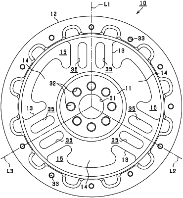
1. A flexible flywheel comprising:
a shaft fastening portion having a ring shape with a round hole at a center of the shaft fastening portion for receiving an end portion of a shaft of a rotating machine;
an inertia ring having an annular shape and an inner diameter greater than an outer diameter of the shaft fastening portion and including an inner surface opposite a periphery of the shaft fastening portion;
a first spoke portion extending from a first portion of the periphery of the shaft fastening portion to a first portion of the inner surface of the inertia ring, the first spoke portion having flexibility and a thickness, measured in an axial direction of the shaft, smaller than a thickness of the inertia ring;
a second spoke portion extending from a second portion of the periphery of the shaft fastening portion to a second portion of the inner surface of the inertia ring, the second spoke portion having flexibility and a thickness, measured in the axial direction of the shaft, smaller than the thickness of the inertia ring;
a first weight portion protruding outward from a third portion of the periphery of the shaft fastening portion opposite from the first portion of the periphery of the shaft fastening portion and including a first distal end opposed to the inner surface of the inertia ring and separated from the inner surface of the inertia ring;
a second weight portion protruding outward from a fourth portion of the periphery of the shaft fastening portion opposite from the second portion of the periphery of the shaft fastening portion and including a second distal end opposed to the inner surface of the annular inertia ring and separated from the inner surface of the inertia ring;
a third spoke portion extending from a fifth portion of the periphery of the shaft fastening portion to a third portion of the inner surface of the inertia ring, the third spoke portion having flexibility and a thickness, measured in the axial direction of the shaft, smaller than the thickness of the inertia ring; and
a third weight portion protruding outward from a sixth portion of the periphery of the shaft fastening portion opposite from the third portion of the periphery of the shaft fastening portion and including a third distal end opposed to the inner surface of the annular inertia ring and separated from the inner surface of the inertia ring, wherein
the shaft fastening portion, the inertia ring, the first spoke portion, the second spoke portion, the first weight portion, and the second weight portion are integrally formed by casting or forging,
the first spoke portion, the second spoke portion, the third spoke portion, the first weight portion, the second weight portion, and the third weight portion are separated from one another in the circumferential direction of the shaft fastening portion,
the first weight portion is between the second spoke portion and the third spoke portion,
the second weight portion is between the first spoke portion and the third spoke portion, and
the third weight portion is between the first spoke portion and the second spoke portion.
|