| CPC F16C 29/10 (2013.01) [F16C 29/06 (2013.01)] | 8 Claims |

|
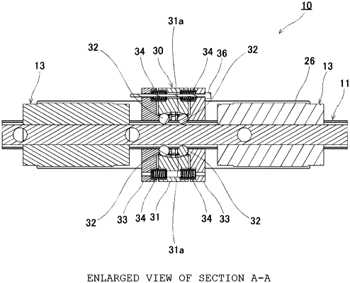
1. A motion guide device comprising: a clamper mechanism, a track member formed to extend in a longitudinal direction, and a movable member attached to the track member with an interposition of a plurality of rolling elements, the movable member being attached to the motion guide device relatively movable in a reciprocating manner in the longitudinal direction of the track member, the movable member being restrained/non-restrained at any position in the longitudinal direction of the track member to position the movable member with respect to the track member, the clamper mechanism comprising:
a clamper block having a pair of left and right tapered faces opposite to left and right side faces of the track member;
one or more clamper rolling elements arranged between each of the pair of left and right tapered faces included in the clamper block and the left and right side faces of the track member; and
a clamper rolling element holder having a clamper rolling element holding part that holds the clamper rolling elements and is attached to the clamper block with an interposition of an elastic member that exerts an elastic force, wherein
when the elastic force exerted by the elastic member acts in a direction in which the clamper block and the clamper rolling element holder are separated from each other, the clamper rolling elements bite the tapered faces to bring the clamper block into a state restrained to the track member, and
when an external force against the elastic force exerted by the elastic member acts to bring the clamper block and the clamper rolling element holder closer to each other, the clamper rolling elements are brought into a state freely rollable within the tapered faces to bring the clamper block into a state not restrained to the track member.
|