| CPC F04D 29/384 (2013.01) [F24F 1/38 (2013.01); F05D 2240/303 (2013.01); F05D 2240/304 (2013.01); F05D 2250/711 (2013.01); F05D 2250/74 (2013.01)] | 19 Claims |

|
1. An axial-flow fan to be included in an outdoor unit for an air-conditioning apparatus, the axial-flow fan comprising:
a hub that is to be rotated and defines a rotation axis; and
a vane provided on a circumference of the hub,
the vane including
a leading edge forming an edge located forward in a rotating direction,
a trailing edge forming an edge located backward in the rotating direction,
an outer circumferential edge forming an edge at an outer circumference of the vane, and
an inner circumferential edge connected to the hub and forming an edge at an inner circumference that is further inside than an outermost circumference of the vane,
in a section of the vane that is along an axial direction of the rotation axis and along a circumferential direction of the axial-flow fan,
in a case in which an angle formed between a virtual line intersecting the trailing edge and being parallel to the rotation axis and a virtual line representing a direction in which the trailing edge faces is defined as an outlet angle of the vane,
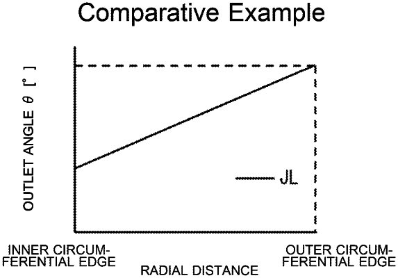
a first diagram is set in which a horizontal axis represents a distance on the trailing edge in a radial direction of the axial-flow fan from the inner circumferential edge to the outer circumferential edge while a vertical axis represents a size of the outlet angle, and
a relationship between the size of the outlet angle and the distance on the trailing edge in the radial direction from the inner circumferential edge is represented as a first line chart,
the vane being shaped such that the first line chart in the first diagram includes a downward convex portion that is convex further downward than a first virtual line chart, the first virtual line chart being a linear line connecting a point representing a size of the outlet angle formed at a point of the trailing edge that is at the inner circumferential edge and a point representing a size of the outlet angle formed at a point of the trailing edge that is at the outer circumferential edge, the first virtual line chart being a linear line representing that the outlet angle increases at a constant rate from the inner circumferential edge to the outer circumferential edge.
|