| CPC F04D 17/122 (2013.01) [F04D 29/4206 (2013.01); F04D 29/444 (2013.01)] | 5 Claims |

|
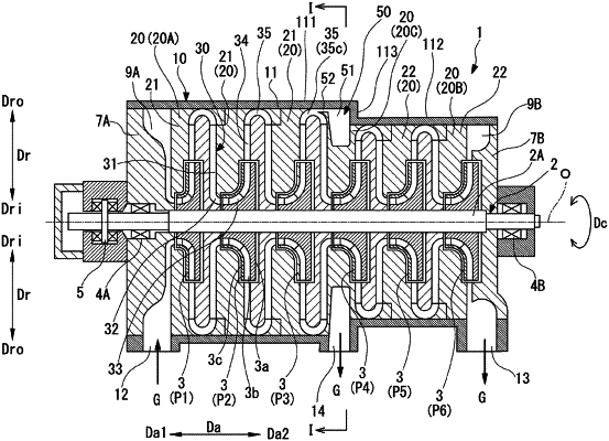
1. A centrifugal compressor comprising:
a rotary shaft extending in an axial direction in which a central axis extends; and
a casing having a suction port formed on a first side in the axial direction in the casing, a discharge port formed on a second side in the axial direction in the casing, and an intermediate discharge port formed between the suction port and the discharge port in the axial direction, wherein
the rotary shaft has a plurality of impellers that are disposed in the casing at a distance in the axial direction, that configured to compress a working fluid supplied from the first side in the axial direction with respect to each of the plurality of impellers, and that configured to discharge the working fluid to an outer side in a radial direction with the central axis as a reference with respect to the each of the plurality of impellers,
the casing has
a plurality of diaphragms formed in a tubular shape extending in the axial direction to cover the each of the plurality of impellers,
an external casing formed in a tubular shape extending in the axial direction to cover the plurality of diaphragms,
a return flow path that is configured to guide the working fluid, which is discharged from each of the plurality of impellers and is flowing toward the outer side in the radial direction, so that a flow direction of the working fluid is directed to an inner side in the radial direction, and
an intermediate scroll that is configured to guide part of the working fluid discharged from one of the plurality of impellers in an intermediate stage which is disposed midway in the axial direction among the plurality of impellers to the intermediate discharge port,
the intermediate scroll has
a scroll flow path formed on the second side in the axial direction with respect to the return flow path, extending in a circumferential direction around the central axis, and connected to the intermediate discharge port at part of the scroll flow path in the circumferential direction, and
an introduction portion connecting the return flow path and the scroll flow path,
the introduction portion is configured to introduce part of the working fluid flowing through the return flow path into the scroll flow path,
in the scroll flow path, an outer flow path forming surface is located on an outermost side in the radial direction and the outer flow path forming surface is formed by a casing inner peripheral surface,
the casing inner peripheral surface faces the inner side of the external casing in the radial direction and faces a diaphragm outer peripheral surface facing the outer side of each of the plurality of diaphragms in the radial direction,
the plurality of diaphragms has
a first diaphragm disposed on the first side in the axial direction in the plurality of diaphragms, and
a second diaphragm disposed on the second side in the axial direction with respect to the first diaphragm and having a smaller outer diameter in the radial direction than an outer diameter of the first diaphragm,
the casing has
a first tubular portion covering the first diaphragm,
a second tubular portion covering the second diaphragm and having a smaller inner diameter in the radial direction than an inner diameter of the first tubular portion, and
a connection wall portion formed between the first tubular portion and the second tubular portion, extending in a direction intersecting the axial direction, and connecting the first tubular portion and the second tubular portion, and
a second side flow path forming surface located on the second side in the axial direction in the scroll flow path is formed by an inner wall surface of the connection wall portion, which faces the first side in the axial direction in the connection wall portion.
|