| CPC F02C 7/232 (2013.01) [F23D 11/383 (2013.01); F23R 3/14 (2013.01); F23R 3/28 (2013.01); F23R 3/343 (2013.01)] | 8 Claims |

|
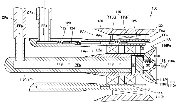
1. A liquid fuel injector comprising:
a cylindrical primary fuel injecting body having a central axis;
an annular shroud concentrically placed radially outside the primary fuel injecting body; and
an annular secondary fuel injecting body placed concentrically with the primary fuel injecting body and the shroud between the primary fuel injecting body and the shroud,
wherein a plurality of inner swirlers placed at equal intervals in a circumferential direction are provided in an annular inner air passage formed between the primary fuel injecting body and the secondary fuel injecting body,
a plurality of outer swirlers placed at equal intervals in the circumferential direction are provided in an annular outer air passage formed between the secondary fuel injecting body and the shroud,
the primary fuel injecting body is formed as a pressure spray-type injector,
the secondary fuel injecting body, the inner air passage, and the outer air passage cooperatively constitute an airblast-type injector,
the inner swirlers and the outer swirlers each include a plurality of guide vanes placed on an upstream side and a plurality of helical vanes placed on a downstream side in a flowing direction of air inside the inner air passage and the outer air passage, respectively,
center lines of profiles of the helical vanes are inclined in the circumferential direction at a substantially constant angle with respect to a direction of the central axis over an entire range from leading edges to trailing edges, and
center lines of profiles of the guide vanes are substantially directed, at the leading edges, in the direction of the central axis and are substantially directed, at the trailing edges, in a same direction as the center lines of the profiles of the helical vanes at the leading edges.
|