| CPC F01D 11/02 (2013.01) [F01D 11/001 (2013.01); F05D 2230/30 (2013.01); F05D 2230/60 (2013.01); F05D 2230/64 (2013.01); F05D 2260/81 (2013.01)] | 9 Claims |

|
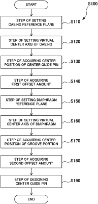
1. A design method of a center guide pin of a rotary machine that includes a rotor, a casing, a diaphragm, a groove portion, and the center guide pin, the rotor being rotatable about an axis, the casing extending in a circumferential direction of the rotor and being vertically separable by a casing dividing surface which is a horizontal plane, the diaphragm being disposed between the casing and the rotor, extending in the circumferential direction of the rotor, and being vertically separable by a diaphragm dividing surface which is a horizontal plane, the groove portion being formed on an outer peripheral surface of the diaphragm so as to extend in an axial direction in which the axis extends, and the center guide pin being fixed to an inner peripheral surface of the casing facing the outer peripheral surface of the diaphragm and capable of positioning the diaphragm with respect to the casing in a horizontal direction orthogonal to the axial direction by being fitted into the groove portion, the design method comprising:
a step of acquiring a plurality of center points of the casing when viewed from the axial direction by measuring the inner peripheral surface of the casing by three-dimensional measurement at a plurality of measurement positions spaced apart from each other in the axial direction, and setting a virtual center axis of the casing based on the plurality of center points of the casing;
a step of acquiring a center position of the center guide pin in the horizontal direction by measuring an outer shape of the center guide pin by three-dimensional measurement;
a step of acquiring, as a first offset amount, an offset amount of the center position of the center guide pin from the virtual center axis of the casing in the horizontal direction;
a step of acquiring a center point of the diaphragm when viewed from the axial direction by measuring the outer peripheral surface of the diaphragm by three-dimensional measurement, and setting a virtual center axis of the diaphragm based on the center point of the diaphragm;
a step of acquiring a center position of the groove portion in the horizontal direction by measuring a shape of the groove portion by three-dimensional measurement;
a step of acquiring, as a second offset amount, an offset amount of the center position of the groove portion from the virtual center axis of the diaphragm in the horizontal direction; and
a step of designing the center guide pin based on the first offset amount and the second offset amount such that a position of the diaphragm in the horizontal direction in a state where the diaphragm is incorporated in the casing is within a tolerance determined with respect to the casing.
|