| CPC C25B 1/26 (2013.01) [C25C 3/02 (2013.01); C25C 7/06 (2013.01); F24V 30/00 (2018.05); H02J 3/28 (2013.01); H02J 15/00 (2013.01); H10N 10/13 (2023.02)] | 16 Claims |

|
1. An energy management method, comprising:
conducting electric energy produced by an energy production plant to an energy storage facility;
applying, in the energy storage facility, the received electric energy to a chemical compound to separate the chemical compound into a first component and a second component, wherein the first component comprises an alkaline metal and the second component comprises a halogen gas;
storing, in the energy storage facility, the first component and the second component separately; and
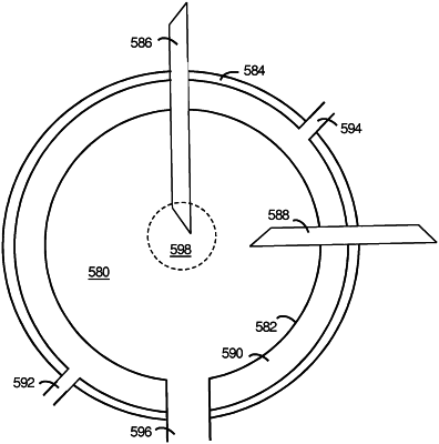
conducting the first component and the second component through first and second ducts, respectively, into a reaction area of an interior space of a spherical reaction chamber to combine the first and second components to re-form the chemical compound and thereby produce energy when needed, wherein the interior space is sealed to be void of substances other than the first and second components and the chemical compound formed by them and is defined by a surface surrounded by a sheath having an enclosed heat exchanging space, wherein the reaction area is located toward a center of the interior space of the reaction chamber to facilitate even distribution of heat generated by the re-forming of the chemical compound to the heat exchanging space, and wherein the first and second ducts are positioned at a right angle to each other in the interior space of the reaction chamber;
conducting the re-formed chemical compound out of the interior space of the reaction chamber through a third duct, the third duct being located below the first and second ducts; and
passing a fluid through the heat exchanging space of the sheath to conduct heat produced in the interior space to the exterior of the reaction chamber.
|