| CPC B64G 3/00 (2013.01) [B64G 1/242 (2013.01); B64G 1/244 (2019.05); G01C 21/24 (2013.01); G06T 7/277 (2017.01); G06T 7/74 (2017.01); B64G 1/245 (2023.08); G06T 2207/30181 (2013.01); G06T 2207/30244 (2013.01)] | 14 Claims |

|
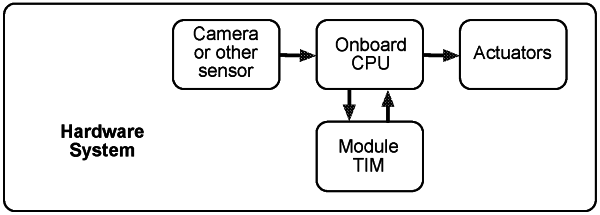
4. A module comprising: a central processing unit programmed to determine an aerospace vehicle's position with respect to the Earth, determining the aerospace vehicle's pose estimation between two points in time and/or attitude with respect to the Earth wherein:
a) determining the aerospace vehicle's position with respect to the Earth comprises:
(i) having the aerospace vehicle acquire, at a known general altitude and at a time from Evening Civil Twilight to Morning Civil Twilight, an image of the Earth comprising at least one terrestrial light feature;
(ii) matching, using Lowe's ratio test, said at least one terrestrial light feature of the image with at least one feature of a terrestrial light data base;
(iii) weighting, to a scale of one, said matched images;
(iv) optionally, calculating a propagated position for said aerospace vehicle using at least one of a Kalman Filter, an Extended Kalman Filter and an Unscented Kalman Filter, and checking the result of said propagated position against the weighting;
(v) using the time and the altitude that said image was taken at to convert said weighted match into inertial coordinates by transforming a state vector containing position and velocity from Earth-Centered-Earth-Fixed (ECEF) coordinates to Earth-Centered-Inertial (ECI) coordinates using the following equations:
rECI=RrECEF
vELI=RvECEF+RrECEF
 R=ωER
where θ represents the Greenwich Apparent Sidereal Time, measured in degrees and computed as follows:
θ=[θm+Δψ cos(εm+Δε)])mod(360°
where the Greenwich mean sidereal time is calculated as follows:
θm=100.46061837+(36000.770053608)t+(0.000387933)t2−(1/38710000)t3
where t represents the Terrestrial Time, expressed in 24-hour periods and the Julian Day (JD):
 wherein the mean obliquity of the ecliptic is determined from:
εm=23°26′21.″448−(46.″8150)t−(0.0″00059)t2+(0.″001813)t3
wherein the nutations in obliquity and longitude involve the following three trigonometric arguments:
L=280.4665+(36000.7698)t
L′=218.3165+(481267.8813)t
Ω=125.04452−(1934.136261)t
and, the nutations are calculated using the following equations:
Δψ=−17.20 sin Ω−1.32 sin(2L)−0.23 sin(2L′)+0.21 sin(2Ω)
Δε=9.20 cos Ω+0.57 cos(2L)+0.10 cos(2L′)−0.09 cos(2Ω)
then using, the equations for the position, r, and velocity, v, in the ECI frame to calculate the position and velocity in the ECEF frame using the dimensions of the earth,
when longitude is calculated from the ECEF position by:
 the geodetic latitude, φgd, is calculated using Bowring's method:
  next the geocentric latitude is calculated from the geodetic,
 where f is the flattening of the planet; e2 is the square of the first eccentricity, or e2=1−(1−f)2; and s=(rxECEF+ryECEF)1/2 such calculation is iterated at least two times to provide a converged solution, known as the reduced latitude, that is calculated by:
 wherein the altitude, hE, above Earth's surface is calculated with the following equation:
hE=(s·cos φ+rzECEF+e2N sin φ)sin φ−N
wherein the radius of curvature in the vertical prime, N, is found with
 (vi) optionally updating said aerospace vehicle's propagated position by using the inertial coordinates in a propagation position and/or an attitude calculation wherein said calculation uses the at least one of a Kalman Filter, an Extended Kalman Filter and an Unscented Kalman Filter;
b) determining the aerospace vehicle's pose estimation between two points in time comprises:
(i) having the aerospace vehicle acquire, at a time from Evening Civil Twilight to Morning Civil Twilight, at least two images of the Earth at different times, each of said at least two images containing at least one common terrestrial light feature;
(ii) comparing said at least two images to find the at least one common terrestrial light feature;
(iii) calculating the aerospace vehicle's pose by first, converting image coordinates of the at least two images that were acquired by a camera to normalized coordinates using the following equations and method, wherein a reference frame of the camera is defined with a first axis aligned with the central longitudinal axis of the camera, a second axis, that is a translation of said first axis and a normalization of said camera's reference frame, a third axis that is a rotation and translation of said second axis to the top left corner of said at least two images with the x-axis aligned with the local horizontal direction and the y-axis pointing down on the side of the at least two images from the top left corner, and wherein said rotation is aided by a calibration matrix of the camera, containing focal lengths of an optical sensor, which maps to pixel lengths,
   (iv) calculating an essential matrix from the normalized coordinates and then recovering the pose from the essential matrix using the following equations, wherein the equation for the epipolar constraint is defined as follows:
xn1T(t×Rxmo)=0
and said equation for the epipolar constraint is rewritten as the following linear equation:
xn1T[tx]Rxno=0
where
 wherein [tx] is saying the translation vector should be skewed (showing an operation) and [t]x is showing post-operation the skewed vector into a matrix
the matrix [t]x is redefined using the Essential Matrix, E:
xn1TExno=0
where
E=R[t]x
and the Essential Matrix is scaled or unscaled and if scaled, then the scale is known from the two images, and reflects six degrees of freedom;
wherein other constraints on the Essential Matrix are the following:
det(E)=0
2EETE−tr(EET)E=0
or, when the epipolar constraint is applied to pixel coordinates, then a Fundamental Matrix, F, is used:
xp1TFxpo=0
said equation is then solved for the Fundamental Matrix and the pose is recovered from the Essential and/or Fundamental Matrices wherein said pose is defined as:
T=[R|t]
(iv) combining a known absolute position and attitude of the aerospace vehicle with the recovered pose to yield an updated attitude and estimated position for the aerospace vehicle wherein said combining step is achieved by using the following equations wherein the attitude, C1 at the second image is defined by
C1=C0+R
wherein C0 and inertial position corresponding to the second image is found by adding the scaled change in position, t, to the previous inertial position:
r1=r0+t.
|