| CPC B25B 23/0035 (2013.01) [B25B 21/02 (2013.01)] | 20 Claims |

|
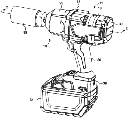
1. An impact tool comprising:
a housing;
a motor supported within the housing;
an anvil extending from the housing, the anvil including
a body rotatable about a longitudinal axis,
a driving end portion configured to receive a tool element over a distal end thereof, and
a bore extending through the driving end portion of the anvil in a direction transverse to the longitudinal axis, the driving end portion including a groove located between the bore and the distal end,
wherein the groove includes a curved portion converging toward the distal end, the groove being configured to receive a friction ring such that the friction ring follows a contour of the groove; and
a drive assembly configured to convert a continuous rotational input from the motor to intermittent applications of torque to the anvil, the drive assembly including a camshaft driven by the motor and a hammer configured to reciprocate along the camshaft.
|