| CPC A63B 22/04 (2013.01) [A63B 21/0056 (2013.01); A63B 21/154 (2013.01); A63B 21/225 (2013.01); A63B 21/4035 (2015.10); A63B 24/0087 (2013.01); A63B 2071/0658 (2013.01)] | 9 Claims |

|
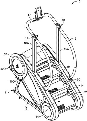
1. An exercising stair step device comprising;
a stationary frame having a pair of spaced support frame legs;
a pair of upstanding handrails with an interconnecting support rail;
an upper drive shaft and a lower drive shaft supported on respective bearing sets between each support frame leg of the pair of spaced support frame legs;
a pair of upper chain engagement sprockets on opposite ends of the upper drive shaft;
a pair of lower chain engagement sprockets on opposite ends of the lower drive shaft;
a pair of step drive chains, each extending around an upper chain engagement sprocket of the pair of upper chain engagement sprockets and a lower chain engagement sprocket of the pair of lower chain engagement sprockets on respective opposing sides of the upper drive shaft and the lower drive shaft;
a plurality of interconnected step assemblies connected between each step drive chain of the pair of step drive chains;
a flywheel drive shaft and support bearing assembly on and extending between the pair of spaced support frame legs in spaced relation to the upper drive shaft, a weighted flywheel disposed on a first end of the flywheel drive shaft and a flywheel pulley disposed on an opposite end of the flywheel drive shaft;
a drive belt in communication with the flywheel pulley;
a drive belt engagement tensioner assembly on the upper drive shaft; and
a pair of magnetic resistant brake assemblies positionally engageable with the weighted flywheel for selective activation via control input levers disposed on the pair of upstanding handrails.
|