| CPC A61B 17/068 (2013.01) [A61B 17/07207 (2013.01); A61B 17/1155 (2013.01); A61B 17/320016 (2013.01); H02J 7/0024 (2013.01); H02J 7/0068 (2013.01); A61B 2017/00017 (2013.01); A61B 2017/00398 (2013.01); A61B 2017/00734 (2013.01); A61B 2017/07271 (2013.01); A61B 2017/07278 (2013.01); A61B 2017/07285 (2013.01); A61B 2017/2923 (2013.01); A61B 2017/2927 (2013.01); A61B 2017/320052 (2013.01); H02J 7/34 (2013.01)] | 20 Claims |

|
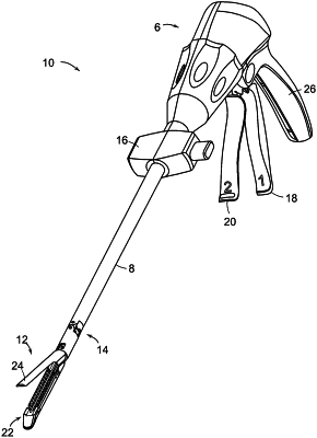
1. A surgical instrument comprising:
an end effector comprising a moveable firing driver;
an electric motor for actuating the firing driver; and
a motor control circuit for controlling the motor, wherein the motor control circuit comprises:
a power source connected to the motor for electrically powering the motor;
a charge accumulator device; and
a switching circuit connected to the power source and the charge accumulator device, wherein the switching circuit comprises:
a first switch for selectively connecting the charge accumulator device to the power source not in series to charge the charge accumulator device; and
a second switch for selectively connecting the charge accumulator device in series with the power source to provide additional power to the motor, wherein, when the first switch is selectively connecting the charge accumulator device to the power source, the second switch is not selectively connecting the charge accumulator device in series with the power source.
|