| CPC A61B 17/7233 (2013.01) [A61B 17/0401 (2013.01); A61B 17/0642 (2013.01); A61B 17/0644 (2013.01); A61B 17/1728 (2013.01); A61B 17/7037 (2013.01); A61B 17/8004 (2013.01); A61B 17/809 (2013.01); A61B 17/8042 (2013.01); A61B 17/8052 (2013.01); A61B 17/8057 (2013.01); A61B 17/8061 (2013.01); A61B 17/84 (2013.01); A61B 17/846 (2013.01); A61B 17/848 (2013.01); A61B 17/8605 (2013.01); A61B 17/8625 (2013.01); A61B 17/888 (2013.01); A61B 17/8863 (2013.01); A61B 17/8888 (2013.01); A61F 2/34 (2013.01); A61B 17/725 (2013.01); A61B 17/8085 (2013.01); A61B 17/863 (2013.01); A61B 2017/044 (2013.01); A61B 2017/0427 (2013.01); A61F 2002/3401 (2013.01)] | 20 Claims |

|
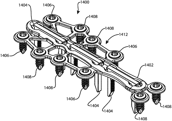
9. A bone fixation system, comprising:
(i) a stabilizing member comprising:
an obverse side;
a reverse side opposite the obverse side; and
a plurality of elongated receivers aligned with each other along a direction, each of the elongated receivers being elongate along the direction, and each of the elongated receivers having an opening on the obverse side, wherein the perimeter of the opening is continuously surrounded by the obverse side;
(ii) a plurality of dynamic elements, each of the dynamic elements comprising:
an elongated bridge extending between a first bridge end and a second bridge end, wherein the bridge is configured to be received by a respective one of the elongated receivers; and
at least one leg coupled to the bridge and extending from the bridge to a free end, wherein the respective one of the elongated receivers and leg are configured so that the leg can extend through the reverse side of the stabilizing member when the bridge is received by the respective one of the elongated receivers;
wherein each of the dynamic elements is configured to be held in an elastically deformed state as it is being received by the respective one of the elongated receivers, and to transition towards a relaxed state after it is received by the respective one of the elongated receivers so as to apply a compressive force from the free end.
|