| CPC A47B 47/0041 (2013.01) [A47B 47/0083 (2013.01); A47B 96/1441 (2013.01)] | 4 Claims |

|
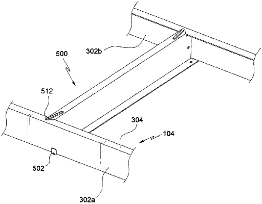
1. A reinforcement beam for a prefabricated shelf having vertical frames and horizontal frames, the horizontal frames having a connection portion fastened to the vertical frames at end portions of the connection portion, and an abutment portion formed integrally with the connection portion and supporting a support plate, the connection portion having an outer side surface and an inner side surface substantially vertical to the abutment portion, the reinforcement beam comprising:
a first horizontal member;
a second horizontal member;
a vertical member formed between the first horizontal member and the second horizontal member and integrally with the first horizontal member and the second horizontal member;
a locking portion formed on each of opposite ends of the second horizontal member and configured to be caught on the abutment portion of the horizontal frames, the locking portion being formed in an inclined shape so that a length of a border portion between the vertical member and the second horizontal member is shorter than a length of the second horizontal member for the locking portion to be placed on an upper surface of the abutment portion of the connection portion;
a pulling portion formed on each of opposite ends of the first horizontal member, wherein the pulling portion is bent upward in a direction toward the locking portion substantially at a right angle, and configured to contact and support a lower outer side surface of the connection portion; and
a side surface support portion formed on each of opposite ends of the vertical member in a longitudinal direction of the vertical member and configured to contact and support an inner side surface of the connection portion under the abutment portion thereof with the locking portion placed on the upper surface of the abutment portion.
|