| CPC A44B 19/14 (2013.01) | 20 Claims |

|
1. A releasable fastener comprising:
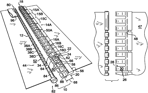
a first connector and a second connector that are selectively configurable between a connected state and a disconnected state, wherein the second connector slidably inserts into the first connector in the connected state;
the first connector comprising a plurality of connected tubular bodies, wherein each tubular body of the plurality of connected tubular bodies includes a tubular-wall having a tubular-wall first end, a tubular-wall second end, an exterior-facing surface, and an interior-facing surface;
wherein each tubular-wall first end of a respective tubular body and a tubular-wall second end of a respective adjacent tubular body are axially aligned along a length direction of the first connector;
wherein the plurality of connected tubular bodies collectively includes a first-connector first end and a first-connector second end;
wherein the axial alignment of the plurality of connected tubular bodies constructs a continuous partially enclosed receiving channel configured to slidably receive the second connector;
wherein the each tubular body of the plurality of connected tubular bodies includes a respective slot extending entirely from the exterior-facing surface to the interior-facing surface and from the tubular-wall first end to the tubular-wall second end;
wherein each respective slot includes a slot width measured from one side of the respective slot to the other side of the respective slot in a radial direction transverse an axis of the first connector; and
the second connector comprising a plurality of connected insert pins, wherein each insert pin of the plurality of connected insert pins and an adjacent insert pin are axially aligned along a length direction of the second connector.
|