| CPC G09G 3/3275 (2013.01) [G09G 3/3266 (2013.01); G09G 2310/0278 (2013.01)] | 20 Claims |

|
1. A display device comprising:
a display panel including a plurality of pixels, which are connected to a plurality of data lines and a plurality of scan lines, wherein a first display area and a second display area, which operate at different frequencies from each other in a multi-frequency mode, are defined in the display panel;
a data driver which drives the plurality of data lines;
a scan driver which drives the plurality of scan lines; and
a driving controller which controls the data driver and the scan driver,
wherein
wherein the first display area includes a boundary area, which adjacent to the second display area, and a non-boundary area, which is not adjacent to the second display area,
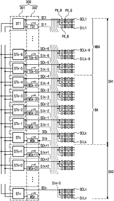
the scan driver includes a first scan circuit outputting a plurality of first scan signals and a second scan circuit outputting a plurality of second scan signals,
the driving controller generates boundary compensation data by compensating for boundary image signals, which are input to correspond to a boundary area of the first display area in the multi-frequency mode, wherein the boundary area is a portion of the first display area adjacent to the second display area,
the driving controller drives the data driver based on a compensation image signal including the boundary compensation data, and
the second scan circuit includes:
a plurality of transmission circuits arranged to correspond to the non-boundary area, wherein the plurality of transmission circuits outputs a part of the plurality of second scan signals in the multi-frequency mode; and
a plurality of masking circuits arranged to correspond to the boundary area and the second display area, wherein the plurality of masking circuits masks a remaining part of the plurality of second scan signals in the multi-frequency mode.
|