| CPC F28D 15/02 (2013.01) [H05K 7/20409 (2013.01); F28D 15/0275 (2013.01); G06F 1/20 (2013.01); H01L 23/367 (2013.01); H05K 7/20 (2013.01); H05K 7/20127 (2013.01)] | 11 Claims |

|
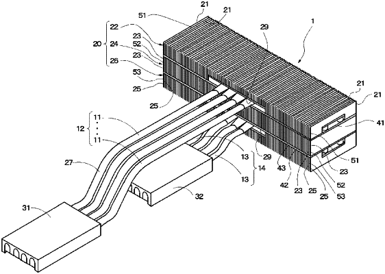
1. A cooling device, comprising:
a heat-radiating fin group having a plurality of heat-radiating fins that are arranged parallel to each other in a first direction;
one or more of first heat pipes, one end of each first heat pipe being configured to be thermally connected to a first heat-generating element, another end of each first heat pipe being thermally connected to the heat-radiating fin group; and
one or more of second heat pipes, one end of each second heat pipe being configured to be thermally connected to a second heat-generating element, another end of each second heat pipe being thermally connected to the heat-radiating fin group,
wherein said another end of each of the first heat pipes is inserted to the heat-radiating fin group and has a bending part in the inserted another end so that respective inserted another ends of said one or more of first heat pipes are disposed on a plane parallel to the first direction and defined in the heat-radiating fin group and have portions parallel to the first direction,
wherein said another end of each of the second heat pipes is inserted to the heat-radiating fin group and has a bending part in the inserted another end so that respective inserted another ends of said one or more of second heat pipes are disposed on said plane parallel to the first direction and defined in the heat-radiating fin group and have portions parallel to the first direction,
wherein the heat-radiating fin group includes a first heat-radiating fin group thermally connected to said another end of each first heat pipe, a second heat-radiating fin group, and a third heat-radiating fin group thermally connected to said another end of each second heat pipe,
wherein the first heat-radiating fin group, the second heat-radiating fin group, and the third heat-radiating fin group are layered on top of one another in that order such that the second heat-radiating fin group receive heat from whichever, between the first heat-radiating fin group and third heat-radiating fin group, has received a relatively greater heat load,
wherein said one or more of first heat pipes are provided in a plurality, and said one or more of second heat pipes are provided in a plurality,
wherein said one ends of the first heat pipes are bundled together and arranged side-by-side in a second direction, which differs from or is the same as the first direction, so as to be thermally connected to the first heat-generating element, and each of the one ends of the first heat pipes is deformed such that a cross-sectional shape thereof is elongated in a direction perpendicular to the second direction, and
wherein said one ends of the second heat pipes are bundled together and arranged side-by-side in a third direction, which differs from or is the same as the first or second direction, so as to be thermally connected to the second heat-generating element, and each of the one ends of the second heat pipes is deformed such that a cross-sectional shape thereof is elongated in a direction perpendicular to the third direction.
|