| CPC F04C 18/107 (2013.01) [E21B 43/121 (2013.01); F04C 23/001 (2013.01); F04C 27/008 (2013.01); F04C 29/12 (2013.01); F04D 17/12 (2013.01); F04D 29/057 (2013.01); F04D 29/162 (2013.01); F04D 29/4213 (2013.01); F04C 2240/10 (2013.01); F04C 2240/20 (2013.01); F04C 2240/30 (2013.01); F04C 2240/50 (2013.01); F04C 2240/54 (2013.01); F04C 2240/60 (2013.01); F04C 2240/802 (2013.01); F04D 3/02 (2013.01)] | 11 Claims |
|
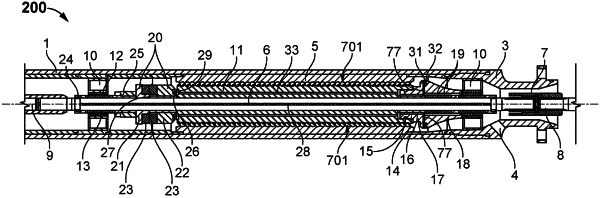
1. An apparatus for a submersible screw pump, the apparatus comprising:
a cylindrical pump housing;
a cylindrical stator having an internal surface that includes a screw thread, wherein the cylindrical stator is rotationally fixed inside of the cylindrical pump housing;
a cylindrical rotor disposed inside of the cylindrical stator, wherein the rotor has a screw thread and the screw thread of the rotor is formed in an opposite direction in relation to the screw thread of the stator, wherein the rotor has an external surface having a shape and the internal surface of the stator has rounded shapes without rectangular edges to obtain high speed performance of the apparatus with reduced vortices, wherein a gap between the internal surface of the stator and the external surface of the rotor is within a range of 0.1-0.2 millimeters;
a first rotor shaft causes the rotor to spin;
a discharge end of the rotor is configured with a hole to discharge production fluid;
an intake end on the pump housing is configured with a hole to allow intake of production fluid to flow into the spinning rotor, wherein the production fluid received into the spinning rotor is compressed by the spinning rotor starting at an initial intake fluid pressure and rising to a higher discharge fluid pressure, wherein the compression of the production fluid by the spinning rotor creates an axial force on the first rotor shaft that is opposite to the direction of fluid flow of the production fluid from the intake end of the rotor to the discharge end of the rotor;
a first thrust bearing attached to the first rotor shaft on the intake end of a first modular pump stage of the apparatus;
a discharge thrust bearing attached to the first rotor shaft on the discharge end of the first modular pump stage;
an unloading thrust bearing attached to the first rotor shaft positioned between the intake thrust bearing and the intake end of the rotor;
a cavity formed in the unloading thrust bearing that is configured to receive the production fluid from the discharge end of the rotor;
rotor fluid channels located inside of the rotor that are positioned substantially half way between the first rotor shaft and an outside edge of the rotor, wherein the rotor fluid channels are disposed between the discharge end of the rotor and the unloading thrust bearing cavity, wherein a counter action against axial force on the rotor shaft is provided by the production fluid in the rotor fluid channels flowing from the discharge end of the rotor into the cavity in the unloading thrust bearing, wherein the production fluid in the cavity presses against the unloading thrust bearing thereby counteracting and reducing the axial force on the rotor shaft; and
wherein the exterior surface of the stator further comprises stator channels that include the rounded shapes without the rectangular edges and the rotor further includes rotor blades, wherein each of the rounded shapes of the stator channels comprises semicircular shape.
|