| CPC E06B 9/322 (2013.01) [E06B 9/303 (2013.01); E06B 9/382 (2013.01); E06B 9/384 (2013.01)] | 4 Claims |

|
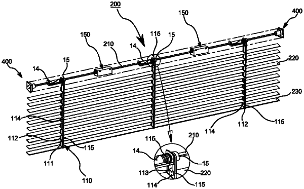
1. A cordless operating safety blind, comprising:
ladder cords in which conical fabric tubes and fabric bodies are formed in several layers, the fabric bodies including longitudinal ends at which tilting cords are located, the conical fabric tubes having insertion holes, the fabric bodies including insertion grooves in which slats are inserted, the conical fabric tubes being formed through centers of tops of insertion grooves, and lift cords inserted in the insertion holes;
a rotary body having a central shaft fastened to the lift cords;
a driving unit in which a rotary gear disposed in a groove of a body and an elastic gear in which a hook of a plate spring is disposed are engaged with each other thereby forming a bevel gear mechanism and a restoring force of the plate spring is changed in direction by 90 degrees by way of the bevel gear mechanism; and
a cover having holding protrusions preventing movement of the rotary gear, the elastic gear, and the plate spring;
wherein the central shaft is rotatably disposed in shaft holes of the rotary body and the rotary gear, and end caps are disposed at both ends of the central shaft, and
wherein the end cap includes:
a cap having a shaft coupler formed at a center of a base protrusion having a plurality of fastening grooves to be fitted on the central shaft, and having a spring having a step and fitted on an outer side of the shaft coupler;
an end cap cover disposed in the shaft coupler, having a step therein, and having a plurality of fastening protrusions on an outer side of a front;
a rotary member having a locking step therein and a protrusion having a plurality of grooves on a front;
a supporting member having a fastening portion at a front disposed on the locking step of the rotary member and having a fastening groove and locking protrusions for fastening a step of the spring;
a shaft fixer disposed on a front of the rotary member and having a rectangular shaft hole at a center;
a main spring having an end fastened to an outer side of the rotary member and the other end fixed inside a step of the end cap cover; and
a lid having a plurality of fastening grooves therein, having a fixing protrusion on an open rear to fix the end cap cover by fastening the fixing protrusion to a fastening groove of the cap.
|