| CPC B62D 33/0633 (2013.01) [B60K 15/03 (2013.01); B60N 3/04 (2013.01); B60N 3/048 (2013.01); B62D 25/10 (2013.01); B62D 33/0617 (2013.01); E02F 3/325 (2013.01); E02F 9/006 (2013.01); E02F 9/0858 (2013.01); E02F 9/0883 (2013.01); E02F 9/0891 (2013.01); E02F 9/16 (2013.01); B60H 1/00378 (2013.01); B60K 11/04 (2013.01)] | 5 Claims |

|
1. A working machine, comprising:
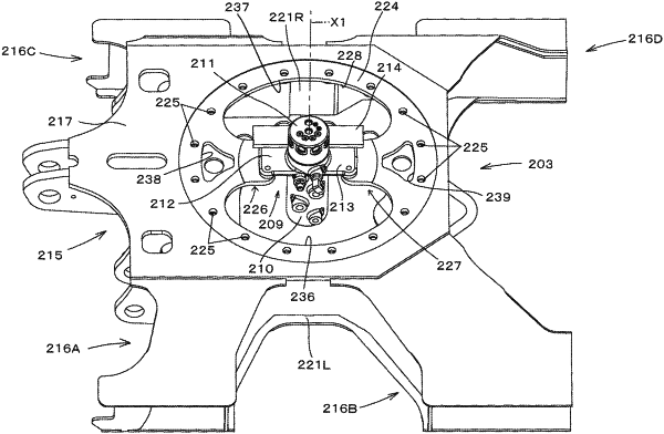
a traveling frame provided with a top plate having an opening;
a swivel base arranged on the traveling frame and configured to be turned about center of the opening as a turn axis; and
a swivel joint arranged at the center of the opening,
wherein the top plate includes:
a first joint support portion protruding toward the center of the opening and supporting the swivel joint; and
a second joint support portion protruding toward the center of the opening from a position opposite to, across the center, the first joint support portion and supporting the swivel joint,
wherein the first joint support portion has a first opening portion penetrating from an upper surface to a lower surface of the first joint support portion,
wherein the second joint support portion has a second opening portion penetrating from an upper surface to a lower surface of the second joint support portion,
wherein the swivel joint includes a first fixing portion and a second fixing portion, the first fixing portion protruding in one horizontal direction, the second fixing portion protruding in an opposite horizontal direction that is opposite to the one horizontal direction,
wherein the first joint support portion includes a first base portion and a first attachment portion which has the first fixing portion placed and attached thereon, the first base portion extending from a circumferential edge of the opening to a midway portion of the first joint support portion in a direction in which the first joint support portion protrudes the first attachment portion extending from the first base portion to a distal end portion of the first joint support portion in the direction in which the first joint support portion protrudes,
wherein the second joint support portion includes a second base portion and a second attachment portion which has the second fixing portion placed and attached thereon, the second base portion extending from the circumferential edge of the opening to a midway portion of the second joint support portion in a direction in which the second joint support portion protrudes, the second attachment portion extending from the second base portion to a distal end portion of the second joint support portion in the direction in which the second joint support portion protrudes,
wherein the first opening portion is in the first base portion,
and wherein the second opening portion is in the second base portion.
|