| CPC H03L 7/0991 (2013.01) [H02M 1/0025 (2021.05); H02M 3/158 (2013.01); H03L 7/07 (2013.01); H03L 7/081 (2013.01); H03L 7/091 (2013.01); H03L 7/10 (2013.01)] | 20 Claims |

|
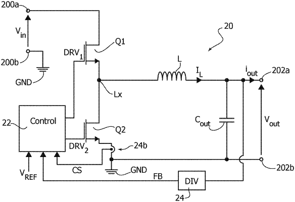
1. A control circuit for a switching stage of an electronic converter configured to provide an output voltage, the control circuit comprising:
a first terminal configured to provide a drive signal to a corresponding electronic switch of said switching stage;
a second terminal configured to receive a first feedback signal proportional to said output voltage from a feedback circuit;
a driver circuit configured to generate said drive signal as a function of a Pulse-Width Modulation (PWM) signal; and
a PWM signal generator circuit configured to generate said PWM signal as a function of said first feedback signal and a reference voltage, wherein said PWM signal generator circuit comprises:
a first current-controlled oscillator having an input terminal configured to receive a first current and generate a first clock signal as a function of said first current;
a second current-controlled oscillator having an input terminal configured to receive a second current and generate a second clock signal as a function of said second current;
a first operational transconductance amplifier configured to provide at a first amplifier output a third current indicative of a difference between said reference voltage and said first feedback signal, wherein said first amplifier output of said first operational transconductance amplifier is connected to said input terminal of said first current-controlled oscillator; and
a phase detector having inputs coupled to said first oscillator and said second oscillator and providing at an output said PWM signal;
wherein said PWM signal generator circuit further comprises:
a first bias current generator configured to provide a first bias current at a first bias output;
a second bias current generator configured to provide a second bias current at a second bias output; and
a switching circuit configured to receive a switch clock signal and:
when a logic level of said switch clock signal has a first logic level, connect the first bias output of said first bias current generator to the input terminal of said first current-controlled oscillator and connect the second bias output of said second bias current generator to the input terminal of said second current-controlled oscillator, and
when the logic level of said switch clock signal has a second logic level, connect the first bias output of said first bias current generator to the input terminal of said second current-controlled oscillator and connect the second bias output of said second bias current generator to the input terminal of said first current-controlled oscillator.
|